


2. Lay out the pistons and connecting rods assemblies and new piston rings in such a way that the set of rings corresponds to the cylinder on which the clearance will be measured.
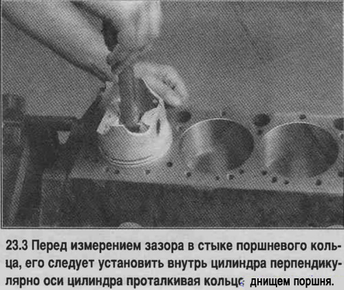
3. Insert the top ring into the first cylinder and push it inward with the piston bottom so that the ring inside the cylinder becomes perpendicular to its axis (see photo). The ring must be in the correct part of the cylinder, in a position corresponding to the BDC of the piston stroke.
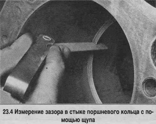
4. The gap in the piston ring joint is measured with feeler gauges and is equal to the total thickness of the feeler gauges inserted into the gap (see photo). The feeler gauges should pass through the gap with a slight force. Compare the result with the standard value. If the gap differs from the norm, check the correct selection of rings.
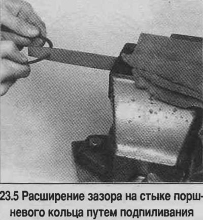
5. If the gap in the piston ring joint is too small, increase it by filing the ends with a file (see photo).
6. The gap should not exceed 0.1 mm, regardless of the engine type. However, you should make sure that the rings are selected correctly.
7. Repeat the measurements for each ring installed in the first cylinder, and for each ring installed in the remaining cylinders. Store the pistons and rings so that they are installed in the cylinder in which the joint clearance was checked.
8. Install the rings on the pistons.
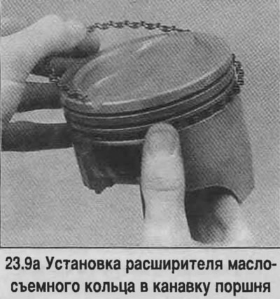
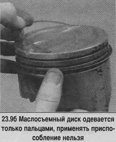
9. The oil scraper ring is installed first (the lowest on the piston). This ring consists of three parts. Install the spacer/expander into the groove (see photo). If the piston has a locking pin to prevent the ring from turning on the piston, make sure there is a pin that is pressed into the hole inside the piston groove. Then install the lower disc of the oil scraper ring. When installing oil scraper discs, do not use a device for putting on rings, as they may break. Insert one end of the oil scraper disc into the piston groove, between the separator and the horizontal platform of the groove, and, firmly holding the end of the disc inserted into the groove, insert the second end of the disc into the groove with your finger (see photo). Proceed in exactly the same way to install the second oil scraper ring disc.
10. After installing all the oil scraper ring parts, make sure that the upper and lower discs rotate freely in the groove.
11. Install the middle ring (number 2). This ring has a stamped mark that should face the piston bottom. Insert the ring into the device and move the ring into the middle groove of the piston (see photo).
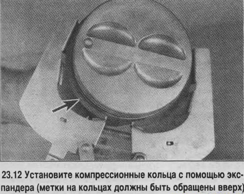
Attention! When installing, the rings are oriented in accordance with the instructions on the packaging. Do not confuse the upper and lower compression rings, as they have different cross-section profiles.
13. Install the upper compression ring in the same way.
14. Install the rings on the remaining pistons in the same order.
[The original text can be found on the website: «ChevyMan»]