


Note: Since there is not enough room in the vehicle's engine bay to remove the camshaft, the engine is removed from the vehicle and mounted on a stand for this procedure.
Checking the lift height of the cam contour
With the cylinder head installed See Illustration 12.3.
1. In order to check the degree of wear of the camshaft lobes before removing the camshaft, the lift of the cam contour should be checked. Remove the valve covers (for 3.1L engine - see section 5, part 2.1; for 3.8 l engine - see section 5, part 2.2).
2. Set piston N1 to TDC on the compression stroke (3.1L engine: see section 3, parts 2.1; 3.8L engine: see section 3, part 2.2).
3. Starting with the valves of cylinder 1, attach a dial indicator to the engine and position the plunger against the top surface of the first rocker arm. The plunger should be in line with the push rod (see illustration).
12.3 To check the lift height of the cam contour, place the plunger of the indicator directly above the push rod (on one line)
4. Set the indicator scale to zero, then slowly turn the crankshaft in the direction of rotation (clockwise), until the indicator arrow stops and starts moving in the opposite direction. The stopping point corresponds to the maximum lift of the cam contour.
5. Record the reading for future reference and return the piston to TDC on the compression stroke.
6. Move the indicator to the other rocker arm of cylinder 1 and repeat the check. Don't forget to record the results for each valve.
7. Repeat the testing procedure for the remaining valves. Since each piston must be at TDC on the compression stroke, take measurements by moving from cylinder to cylinder in accordance with the spark firing sequence of the cylinders.
8. After completing the check, compare the results with the "Technical Data" at the beginning of the chapter. If the cam lift is less than the prescribed value, then the cams are worn, which means that the camshaft needs to be replaced.
With the cylinder head removed See Illustration 12.9.
9. If the cylinder head has already been removed, an alternative method of measuring the cam contour can be used. Remove the camshaft as described later in this section. Using a micrometer, measure the maximum cam contour dimension (from base to highest point). Then measure the base diameter in a direction perpendicular to the direction of the previous measurement (see illustration). Take these measurements for all cams and record the results.
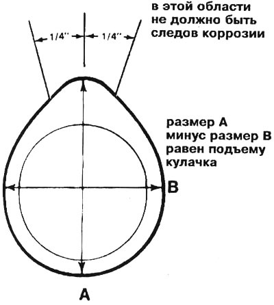
12.9 To check the cam lift height, measure the maximum (A) and minimum (B) diameters - subtract the minimum diameter from the maximum diameter to obtain the lift value
10. Subtract the base diameter value from the cam contour height. This difference is equal to the lift of the cam contour. See point 8 above.
Removal
11. Remove the timing chain and sprockets, tappets and tappet rods (3.1L engine: see section 2.1, sections 5, 10, 13 and 14; 3.8L engine: see part 2.2, sections 5, 8, 13 and 16).
12. Loosen the bolts securing the camshaft thrust flange to the cylinder block. Thread long bolts into the bolt holes on the camshaft sprocket to use as a handle when removing the camshaft from the block (see illustration).
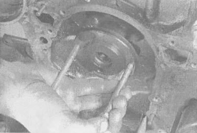
12.12. Thread long bolts into the bolt holes to use as a handle when removing and installing the camshaft
Note: To remove and install the balance shaft (only on 3.1L engine) special equipment required. If the bearings are in poor condition, the balance shaft should be replaced at an auto repair shop (see point 19).
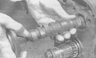
13. Carefully remove the camshaft from the block so that the cams do not damage or scratch the bearings (see illustration).
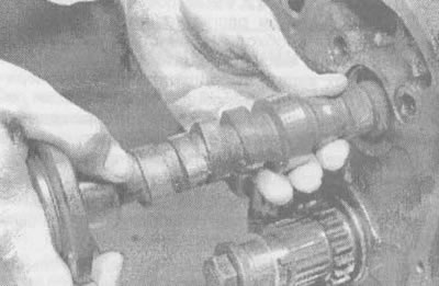
12.13 To check the lift height of the cam contour, place the plunger of the indicator directly above the push rod (on one line)
Examination
14. After removing the camshaft from the engine, it must be cleaned with solvent and dried. Then check the bearing journals for signs of uneven wear, corrosion, or scoring. If the journals are damaged, then most likely the bearing shells in the block are also damaged. In this case, it is necessary to replace both the camshaft and the bearings.
15. Measure the bearing journals using a micrometer (see illustration) to detect excessive wear or out-of-roundness.
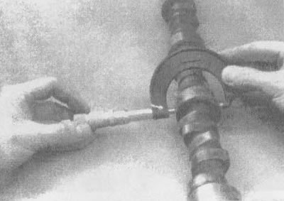
12.15 Measure the journal diameters of the bearings to detect excessive wear or out-of-roundness
16. Inspect the camshaft for signs of thermal discoloration, scratches, corrosion and uneven wear. If the condition of the cams is satisfactory and the cam lift is within acceptable limits, the camshaft is suitable for further use.
17. Check the bearings in the block for wear and damage. Check for scoring, corrosion and discoloration.
18. The inside diameter of each bearing can be determined using a bore gauge and an outside diameter micrometer or an inside diameter micrometer. By subtracting the journal diameter of the bearing shaft from the inner diameter of the corresponding bearing, you will get the bearing clearance. If the clearance exceeds the permissible value, it is necessary to install new bearings, regardless of the condition of the old ones.
19. Replacing the balance shaft and camshaft bearings requires special tools and skills, which makes this operation impossible to do at home. Therefore, to ensure that this work is completed efficiently, it is necessary to send the unit to an auto repair shop.
20. Installation and adjustment of the balance shaft gear are described in section 24.