ChevyMan.ru
Mazda Mitsubishi Toyota Land Rover Honda Kia Nissan
English Русский
Български
Беларускі
Український
Српски
Hrvatski
Română
Polski
Slovenský
Magyar
|
Articles | Sitemap | Contacts |


Home   Aveo   Captiva   Cruze   Lacetti   Lanos   Niva   Tahoe   Others  
Orlando 1 (2010-2018) Trailblazer 1 (2001-2008, petrol) Lumina 1 (1989-1994)
  • Home
  • Chevrolet
  • Orlando 1
  • Power unit
  • Fuel and control system
  • Fuel supply system — design description

Fuel supply system — design description (Chevrolet Orlando 1)

            0

The fuel supply system is designed to store fuel reserves, clean the fuel from foreign impurities and supply it to the engine cylinders. The system consists of a fuel tank, a fuel module, a fuel line and a fuel rail with injectors. For ease of inspection and repair, the fuel line tubes are connected using quick-release fittings.

Fuel is stored in a 64-litre fuel tank, which is suspended from the underbody at the rear of the vehicle. The fuel tank filler neck is located in a niche on the right rear fender.

The fuel module supplies fuel from the tank to the pipeline under a stable pressure within 296.4-310.3 kPa. The fuel module is located in the fuel tank and is attached to it with a clamping ring. It combines a submersible fuel pump, fuel pressure regulator, check valve, fuel filter and fuel level indicator sensor. The pump creates pressure in the fuel line immediately after the ignition is turned on, and it automatically turns off after a few seconds if the engine is not started.

Warning! When the engine is running, the fuel in the system is under pressure! Therefore, the safety of the vehicle operation depends on the tightness of the system. If you smell fuel, turn off the engine and inspect the fuel line and its connections for leaks and correct the problem.


The fuel pressure regulator is a bypass valve that limits pressure by draining excess fuel back into the tank. The check valve prevents fuel from draining from the fuel line back into the tank after the engine is turned off, which reduces the crankshaft rotation time during start-up.


A mesh fuel filter is installed on the inlet pipe of the fuel pump, which traps various dirt that gets into the fuel tank along with gasoline. After leaving the pump, the fuel passes through a fine filter. Using contaminated fuel will quickly clog the filters and reduce the operating pressure in the system, which will cause a drop in engine power to the point of complete engine shutdown. If the fuel pump fails, the engine will not start. When the fuel pump relay circuit is faulty, the engine management system malfunction indicator lamp on the instrument cluster comes on.

The fuel level indicator sensor consists of a float on a wire lever and a resistor board, the resistance of which changes depending on the angle of rotation of the lever. Based on the position of the float, the ECU determines the fuel level in the tank and sends information to the instrument panel via the data transmission circuit.

Fuel rail 2 with injectors 3 is located on the intake manifold.

Fuel rail 2 with injectors 3 is located on the intake manifold.


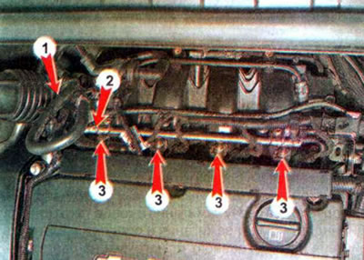
Fuel enters through hose 1 and, passing through the ramp, is distributed to the injectors. Four nozzles (one per cylinder) are fixed to the fuel rail and installed in the holes of the intake manifold. When the ignition is on, 12 V is constantly supplied to one of the injector terminals. To open the injector, the ECU connects the second terminal of the injector to ground. When the injector opens, fuel is injected under pressure into the space above the inlet valve. The ECU regulates the amount of injected fuel by changing the injector opening time. The tightness of the connections is ensured by rubber sealing rings placed on the nozzle pipes. The sealing rings must be replaced each time they are disconnected.

Note: You can check the serviceability of the injector by measuring the resistance at its terminals. A serviceable injector should have a resistance of 11-14 Ohms at a temperature of 10-32°C.

The article was checked: Vladimir Romannikov
This article is available at russian, bulgarian, belarusian, ukrainian, serbian, croatian, romanian, polish, slovak, hungarian

Share information:

Previous articles
Orlando 1: Fuel and control system
Next articles

Air intake system
Electronic control system
Engine management system
Exhaust gas system
Pre-start heater
Emission Control System


See similar articles on the topic of Chevrolet cars:
Features of the design of the engine power supply system Chevrolet Aveo T300 (2012-2018)
Relieving pressure in the fuel supply system Chevrolet Captiva 1 (2006-2018)
Features of the design of the engine power supply system Chevrolet Cruze 1 (2008-2016)
Engine power supply system device Chevrolet Lacetti 1 (2002-2009)
Engine power supply system device Chevrolet Lanos T150 (2002-2009)
Power supply system. General information Chevrolet Niva 1 (2002-2016)
Checking the fuel system Chevrolet Tahoe 1 (1992-2000)
Link in different formats to this page


Visitor comments

No comments yet


How much will 19 + 37 =


Orlando 1 (2010-2018) 
  • General information
  • Introduction to manual
  • User manual
  • Maintenance
  • Troubleshooting
  • Power unit
  • Engine repair
  • Fuel and control system
  • Cooling and lubrication system
  • Ignition system
  • Transmission
  • Clutch
  • Gearbox
  • Drive shafts
  • Chassis
  • Car suspension
  • Steering
  • Brake system
  • Body
  • Exterior (external elements)
  • Doors, locks and windows
  • Electrical equipment
  • Equipment and devices
  • Windscreen wipers
  • Power devices
  • Electrical diagrams


Trailblazer 1 (2001-2008) 
  • General information
  • User manual
  • Troubleshooting
  • Maintenance
  • Power unit
  • Engine in a car
  • Engine overhaul
  • Cooling and heating
  • Fuel and exhaust system
  • Engine electrical equipment
  • Engine control
  • Transmission
  • Automatic gearbox
  • Transfer case
  • Drive shafts and cardan
  • Chassis
  • Brake system
  • Car suspension
  • Steering
  • Body
  • Exterior (external elements)
  • Interior (internal elements)
  • Doors, locks and windows
  • Electrical equipment
  • Equipment and devices
  • Electrical circuits


Lumina 1 (1989-1994) 
  • General information
  • Maintenance
  • Power unit
  • Engine 3.1L V6
  • Engine 3.8L V6
  • Engine overhaul
  • Cooling system
  • Power and exhaust system
  • Fuel injection
  • Engine electrical equipment
  • Reduced exhaust gas toxicity
  • Transmission
  • Automatic gearbox
  • Drive shafts
  • Chassis
  • Brake system
  • Car suspension
  • Steering
  • Body
  • Heating and air conditioning
  • Repair of body elements
  • Doors, covers and windows
  • Interior (internal elements)
  • Electrical equipment
  • Equipment and devices
  • Electrical circuits


ChevyMan.ru © 2017-2026 · Mobile version · Feedback · Site search · Interesting to read · Sitemap: EN BG BY UA RS HR RO PL SK HU

Aveo 2003-2008 · Aveo 2006-2011 · Aveo 2012-2018 · Captiva 2006-2018 · Cruze 2008-2016 · Lacetti 2002-2009 · Lanos 2002-2009 · Niva 2002-2016 · Tahoe 1992-2000 · Tahoe 2000-2014 · Lumina 1 1989-1994 · Trailblazer 1 2001-2008 · Orlando 1 2010-2018 ·
🛡️ For your security and to improve our service, this site uses cookies. You can disable them in your browser.