
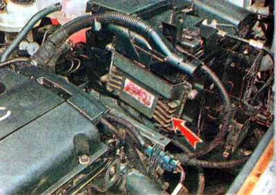
The ECU is the information center of the engine management system. It receives and processes signals from all information sensors of the system and, in accordance with the program embedded in it, controls the operation of all actuators.
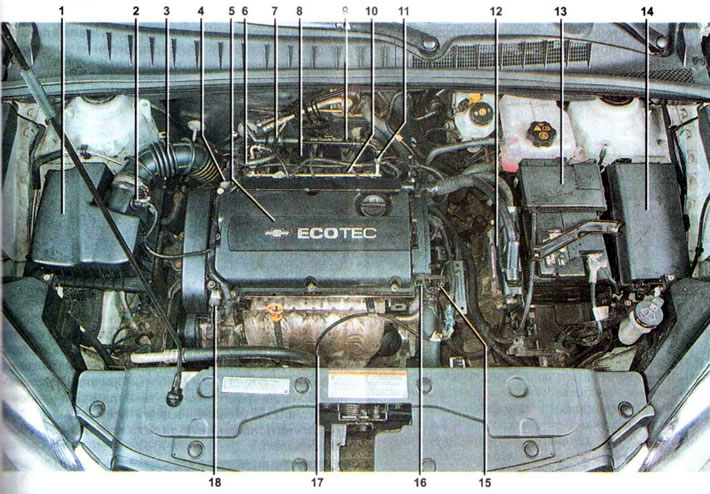
Location of the main elements of the engine management system: 1 - air filter; 2 - intake air temperature sensor; 3 - air supply pipe; 4 - intake camshaft phase change valve; 5 - ignition module and spark plugs (under the overlay); 6 — fuel supply hose; 7 — purge valve of the adsorber; 8 — inlet manifold; 9 — absolute pressure sensor in the intake manifold; 10 - fuel rail with injectors; 11 — nipple for checking pressure in the fuel supply system; 12 — electronic engine control unit (ECU); 13 — battery; 14 - fuse and relay box; 15 - thermostat heater; 16 — exhaust camshaft position sensor; 17 — oxygen concentration control sensor; 18 — exhaust camshaft position sensor
During operation, the ECU monitors the serviceability of all elements and circuits of the engine control system. Having detected a malfunction, the ECU switches the engine management system to the backup operating mode and turns on the engine management system malfunction indicator lamp on the instrument panel.
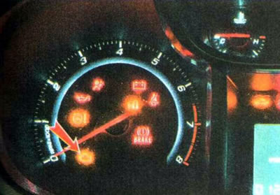
In most cases, the engine will be able to continue to operate, which allows you to get to the repair site under your own power. When driving in this mode, try not to give the engine full load. The codes of detected faults and the vehicle status parameters are stored in the ECU memory. If the fault is not detected during subsequent trips, the control lamp goes out.
The malfunction that has arisen can be determined by diagnosing the engine management system.
The electrical circuits of the engine management system are protected by fuses installed in the fuse and relay blocks.
Note: The ECU is installed in the engine compartment without a protective cover. When washing the engine compartment, cover the ECU with polyethylene. Moisture getting on the contacts of its connectors can cause damage to the electronic components of the ECU.
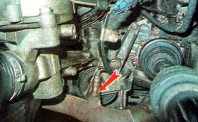
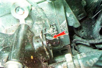
The crankshaft position sensor is installed on the rear wall of the cylinder block near the clutch housing behind the starter.
Crankshaft position sensor
Based on the signals from this sensor, the ECU determines the crankshaft speed and its position. If the sensor malfunctions, the engine starts with difficulty, and information about engine operation is sent to the ECU from the camshaft position sensor. The engine management system malfunction indicator light comes on on the instrument panel.
The position sensors of the intake camshafts 1 and exhaust camshafts 2 are installed in the cylinder head on the left side.
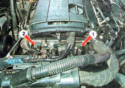
The operating principle of the shaft position sensor is based on the Hall effect. Voltage is applied to the sensor terminals. When the protrusion on the camshaft moves past the end of the sensor, the voltage on the sensor will drop. The voltage surge serves as a reference signal for the engine management system ECU. Based on the sensor signals, the ECU synchronizes the opening of the fuel injectors and the operation of the ignition system in accordance with the working strokes in the engine cylinders.
If the camshaft position sensor fails, the ECU switches to the backup (emergency) operating program. At the same time, the engine management system malfunction indicator lamp lights up on the instrument panel.
The throttle position sensor is combined in one housing with the throttle actuator motor and is mounted on the throttle assembly (for clarity, the air supply pipe has been removed).
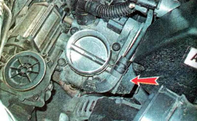
Based on the sensor signal, the ECU determines the amount of valve opening and, depending on this, sends a signal to the electric drive to adjust its position. If the sensor fails, the ECU switches to the backup operating program. At the same time, the engine management system malfunction indicator lamp lights up on the instrument panel.
The gas pedal position sensor is assembled with the pedal.
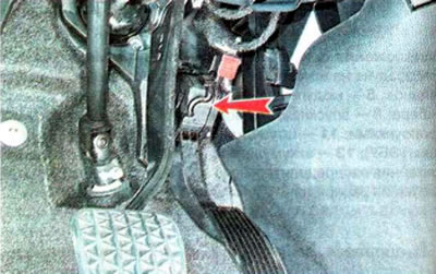
By changing the resistance proportionally to the pedal rotation angle, the sensor informs the ECU about the force with which the driver acts on the gas pedal.
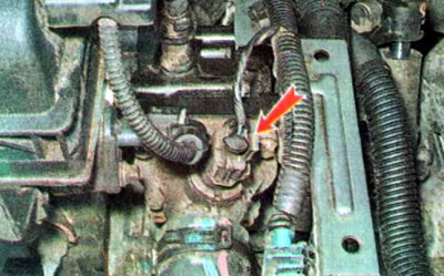
The absolute pressure sensor in the intake manifold is installed in the rear wall of the intake manifold.
The intake air temperature sensor is installed in the air filter outlet pipe.
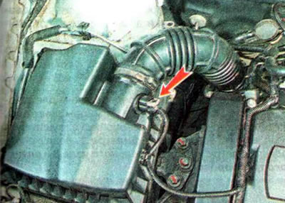
Based on signals from the absolute pressure sensor in the intake manifold and the air temperature sensor at the intake, the ECU calculates the amount of air entering the cylinders and determines the amount of fuel required to form an optimal fuel-air mixture in accordance with the engine operating mode. If any of the two sensors fails, the ECU switches to a backup operating program, and the engine management system malfunction indicator lamp lights up on the instrument panel.
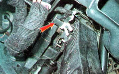
The knock sensor is installed on the rear wall of the cylinder block under the intake manifold.
Based on the signal from the detonation sensor, the ECU adjusts the ignition timing angle, keeping it at the detonation threshold, which is the most optimal for engine operation. If the knock sensor is faulty, the ECU switches to a backup operating program, and the engine management system malfunction indicator lamp lights up on the instrument panel. In this case, detonation may occur (sharp metallic knocks in the engine when the load increases sharply), which is extremely harmful to the engine. Therefore, you should move slowly to the repair site, without sudden acceleration.
Oxygen concentration sensors. The vehicle is equipped with two oxygen concentration sensors that measure the oxygen content in the exhaust gases: one (control) - in the exhaust manifold before the catalytic converter...
...second (diagnostic) - in the exhaust pipe behind the catalytic converter.
Based on the signal from the control sensor, the ECU adjusts the composition of the fuel-air mixture for optimal operation of the catalytic converter, and based on the signal from the diagnostic sensor, it monitors its efficiency. A sign of a faulty sensor is uneven engine operation at idle. If the oxygen concentration sensors are faulty, the ECU switches to a backup operating program, and the engine management system malfunction indicator lamp lights up on the instrument panel.
Coolant temperature sensors are installed in the engine cooling system. One sensor is located in the thermostat housing at the back...
...the second sensor is located in the radiator on the right side.
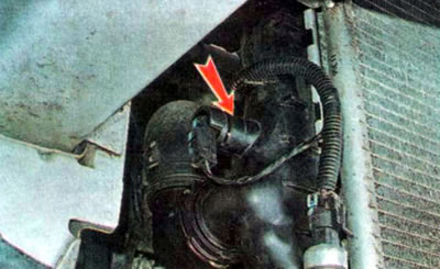
The sensors inform the ECU about the coolant temperature, which is necessary for the correct adjustment of the fuel-air mixture and ignition timing, especially when starting the engine. If one of the coolant temperature sensors fails, the ECU switches to a backup operating program (the cooling system fan turns on at maximum speed), the engine management system malfunction indicator light comes on on the instrument panel. This makes it difficult to start the engine, especially after a long period of inactivity and in cold weather.
The thermostat heater is installed in the thermostat housing on top.
The heating is switched on by the ECU signal, reducing the thermostat opening time.
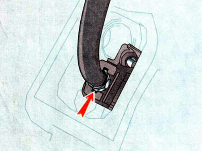
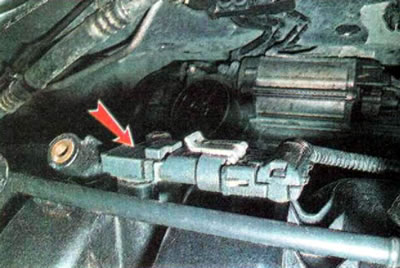
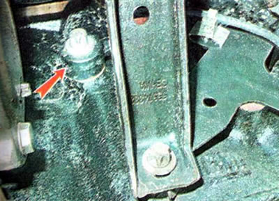
The clutch pedal position sensor is mounted on the pedal bracket. The sensor informs the ECU about the degree of pressure on the clutch pedal.
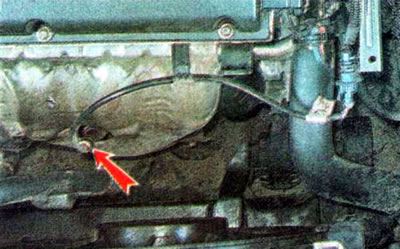
The emergency oil pressure sensor is installed on the front wall of the cylinder block behind the air conditioning compressor of the air conditioning system. The sensor informs the ECU about the decrease in pressure in the engine lubrication system to an unacceptable level.