


General information
1. In some electrical circuits, such as the fuel injection system, horn, starter and fog lamp circuits, current is supplied to the components by passing through a relay. The relay has a low voltage circuit(control chain), which controls the high voltage circuit (power circuit). When a relay fails, the normal operation of the corresponding circuit device is disrupted. Relays are installed in both the outdoor and indoor units (see illustrations 3.1c and 3.1f). If the relay is suspected of being faulty, remove it and test it as described below, or take it to a service station for diagnostics. Defective relays cannot be repaired.
Checking functionality
2. Most relays used in the design of the described vehicles comply with the ISO standard. The numbering of the contact terminals of such relays corresponds to the closed circuits. There are two main types of relays used in these vehicles (see illustrations).
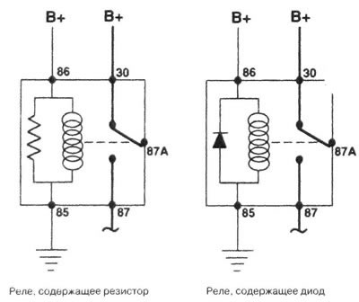
5.2a. The device, numbering of contact terminals and connection diagram of relay circuits corresponding to the ISO standard
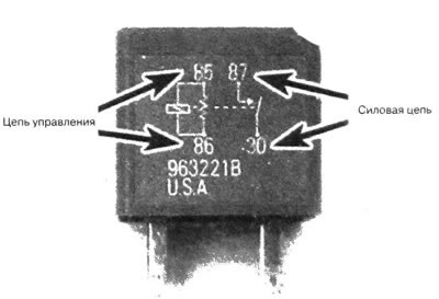
5.2b Most relays have identification markings on the outside for the power and control circuits - a relay with four contact terminals is shown
3. Refer to the electrical diagrams and determine the connection points of the devices for diagnosing the relay. If it is not possible to determine the connection points using the diagrams, determine them using the recommendations below.
4. Most relays have two control circuit contacts (the contact terminals are connected to the relay winding, which, when excited, closes the contacts, which ensures that the power circuit is switched on). The remaining relay contacts belong to the power circuit (they are closed when the control circuit winding is excited).
5. Contacts 85 and 86 belong to the control circuit. If the relay contains a diode, contact 86 should be connected to the positive battery terminal (B+) and contact 85 to the ground circuit. The corresponding contacts of the relay containing the resistor are connected in the same way.
6. Contact 30 is connected to the power circuit (B+) when the circuit is loaded. Contact 87 is connected to the power terminal of the circuit device. If the relay has several additional contact terminals for connection to the power and grounding circuit, these contacts are designated 87A, 87B, 87C, etc.
7. Check the relay control circuit coil using an ohmmeter.
- a) Connect the instrument observing the polarity shown in the illustration for one of the tests, then reverse the ohmmeter electrodes and test for open circuit.
- b) If the relay contains a resistor, the device will display the presence of resistance, which will be equal to the resistance displayed by the device when the electrodes are connected in reverse.
- c) If the relay contains a diode, the resistance registered by the ohmmeter when the electrodes are initially connected will be higher than the resistance displayed by the device when the electrodes are connected in reverse.
- d) If the ohmmeter registers infinite resistance in both directions, replace the relay.
8. Remove the relay and, using an ohmmeter, check the area between the power circuit contact terminals for a break. When the relay is not connected, the circuit between terminals 30 and 87 should be open.
9. Connect a jumper containing a fuse between terminal 86 and the positive battery terminal. Connect another jumper between pin 85 and the ground point. After both jumpers are closed, the relay should click.
10. Without disconnecting the jumpers, check the circuit between the power circuit terminals for an open circuit. In this case, the circuit must be closed between relay contacts 30 and 87.
11. If the relay fails any of the above tests, replace it.