
Before you begin to determine the cause of the malfunction, it is necessary to study the corresponding wiring diagram in order to get a complete understanding of the location of the elements included in this circuit. It is easier to identify possible sources of failure by making sure that other components in the circuit are functioning properly. If multiple devices or circuits fail at the same time, the problem may be with the fuse or ground wire.
Malfunctions in electrical circuits usually arise for simple reasons, for example, due to loose contact in the connectors, a break in the ground loop, a failure of a fuse or relay. Before checking the functionality of the devices on the faulty circuit, inspect the fuses, wires and connectors included in it.
If it is intended to examine a circuit using special equipment and tools, in order to determine the procedure for checking the operability of devices and circuit elements, it is necessary to first study the corresponding wiring diagram.
The main tools used in the process of determining the causes of faults in electrical circuits are a tester or a voltmeter (a 12-volt test light may also be used for some tests) and jumper (preferably with fuse), which is used to bypass an electrical circuit (see illustrations). Before working with the instruments, study the wiring diagram to determine the points at which measurements should be made.
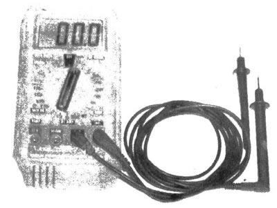
2.5a. Most often, in the process of determining the causes of faults in electrical circuits, a digital multimeter is used, which is used to measure voltage, determine current strength, and also check the circuit for an open circuit
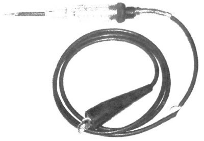
2.5b. When determining the presence of voltage in a circuit, it is recommended to use an easy-to-use test lamp
Voltage measurement
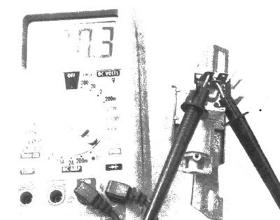
Voltage measurement is carried out when a fault occurs in the electrical circuit. Connect one lead of the tester to the negative terminal of the battery or to one of the ground points. The second tester lead should be connected to the connector on the circuit being tested, preferably the one closest to the battery or fuse (see illustration). If there is voltage in the circuit (or the indicator light is on), this means that the section of the circuit between the corresponding connector and the control race is working. Continue testing the remaining sections of the chain using the same technique. When a point in the circuit is reached at which the voltage is not detected when the tester is connected, the section of the circuit containing the source of the malfunction will be determined. This is the section of circuit between the point where there is no voltage and the previous tested point. Examine this section of the circuit for a malfunction. The malfunction usually lies in a loose connector.
2.6. When using a test lamp, you must connect its wire to the grounding point and touch the probe to the test point of the circuit (plug, wire, socket), turning on the lamp confirms the presence of battery voltage in the circuit
Note: It should be noted that some circuits only operate when the ignition is on (the lock is in position «Ase» or «Run»).
Determining the short circuit point
Remove the short-circuit fuse and connect the test lamp wires to the fuse terminals (make two extension wires with corresponding contact terminals, connect the wires to the contacts in the fuse box and connect a test lamp to the circuit). There should be voltage present in the circuit. Move the wire that may have a short circuit while observing the test light. If the lamp turns off, it means that this section of the circuit is shorted to ground. It is possible that the short circuit occurs due to exposed wiring.
Grounding check
To check whether the circuit device is properly grounded, disconnect the battery and connect one lead of a self-powered ohmmeter or tester to the grounding point. Connect the second wire of the device to the wiring connector or grounding point of the device being tested. The presence of grounding is confirmed by the indicator light coming on or low resistance (up to 50m) in this area.
Checking the circuit for an open circuit
This test is performed to determine the presence of breaks in the electrical circuit. After de-energizing the circuit, check using a test device or a multimeter with an independent power source. Connect the test device to both wires of the circuit (or to the power conductor and circuit grounding point). If the indicator light comes on, it indicates that there is no break in the circuit (see illustration). Low resistance (below 50m) also indicates that the circuit has no breaks. If the light doesn't light up (or resistance is more than 10 ohms), which means the circuit has an open circuit.
2.9. When you turn on the ohmmeter function on the tester, determine the resistance in the section of the circuit between the two contact terminals; when checking for breaks, low resistance indicates their absence; high resistance indicates an open or high resistance source in the circuit
In the same way, you can check any switch by connecting the electrodes of the control device to the contact terminals. When the switch is positioned to close the circuit, the warning light should light up (or low resistance value received).
Locating an open circuit
The location of an open circuit is often not easy to determine by visual inspection, since oxidized wires or open contacts are usually hidden under insulation or the connector housing. Determine the source of the intermittent fault (usually due to a loose connector or damaged insulation) You can just move the wire. If, when moving the wire, the contact in the circuit alternately disappears and appears, it means that the source of the malfunction is located on the section of the circuit that is affected.
Determining the cause of a malfunction in an electrical circuit should take into account the fact that current flows from the battery through wires, switches, relays, fuses and fuse links to each electrical device (lamp, electric motor, etc.), and goes to the grounding point, returning from there again to the battery. Any malfunction in the electrical circuit lies in the wiring and elements through which the current generated by the battery circulates.
Connectors
Most connections in the electrical circuits of the vehicles described are made with plastic multi-pin connectors. As a rule, connector elements have a connecting clamp. Often the elements are connected by a bolt running through the middle of the connector, such as on electrical wiring connectors located under the instrument panel.
Before disconnecting the connector, you must release the connector lock using a small screwdriver. When disconnecting a connector, you should hold its elements with your fingers, but not the wires, since if this recommendation is not followed, damage to both the wiring and the contact pins inside the connector may occur. Before disconnecting, carefully inspect the connector. The connection principle of some fasteners is not easily determined by a quick inspection. Moreover, some connectors have multiple latches.
The elements of each connector are a plug and a socket. When looking at connector labels on wiring diagrams, you need to determine which side they are shown on: the electrical device side or the wiring harness side. The location of the pins of the plug is a mirror image of the pins of the socket, therefore, when viewing the corresponding elements of the connector from different sides (right and left) The display of the location of the contact pins of the plug and socket is the same.
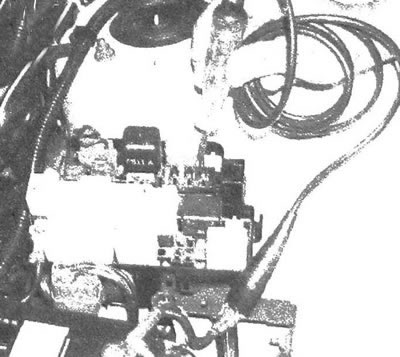
Often it is necessary to measure the voltage in a circuit without disconnecting the connector. Carefully insert a small thin pin into the back of the plug (not tester electrode) so that the pin comes into contact with the corresponding terminal of the connector, then connect the tester electrode to the pin (see illustration). When inserting the pin, do not allow the contact pin to deform, as this may subsequently result in unreliable contact and corrosion on the connector pins. Inserting a small thin pin instead of the tester electrode helps prevent deformation of the connector pin.
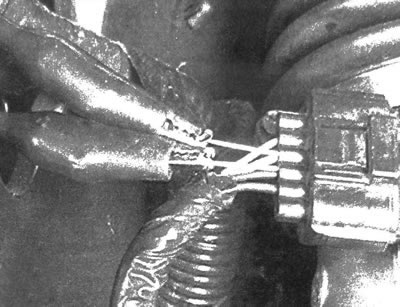
2.15. A small sharp electrode must be inserted for testing (needle type) from the back of the connector into the corresponding contact terminal so that the electrode makes metal contact. Connect the electrodes to the tester and check the functionality of the circuit