
ChevyMan.ru
Mazda Mitsubishi Toyota Land Rover Honda Kia Nissan
English Русский
Български
Беларускі
Український
Српски
Hrvatski
Română
Polski
Slovenský
Magyar
|
Articles | Sitemap | Contacts |


Home   Aveo   Captiva   Cruze   Lacetti   Lanos   Niva   Tahoe   Others  
Orlando 1 (2010-2018) Trailblazer 1 (2001-2008, petrol) Lumina 1 (1989-1994)
  • Home
  • Chevrolet
  • Trailblazer 1
  • Transmission
  • Drive shafts and cardan
  • Drive shaft boot (4WD models) — replacement

Drive shaft boot (4WD models) — replacement (Chevrolet Trailblazer 1)

            0

Contents: Inner CV joint ↧ Outer CV joint ↧
Note: Before the necessary replacement of CV joint boots, analyze the various restoration options. It is recommended to replace the drive shaft with a reconditioned axle shaft, which can be purchased through the exchange fund of the company's service network - this will significantly reduce the waste of time and, possibly, help save money. Regardless of the chosen recovery path. before disassembling, find out about the cost and availability of spare parts.


1. Remove the drive shaft (see subsection 12).

2. Clamp the drive shaft in a vice with fabric pads, the presence of which prevents damage to the axle shaft. Check the CV joint movement in the radial direction. The presence of excessive movement indicates wear of the hinge parts. Make sure the hinges move smoothly in all possible directions. If the boot is torn, disassemble the joint and inspect its components - they may be excessively worn due to lack of lubrication or penetration of foreign particles into the CV joint.

Note: Some models are equipped with a protective cover that is fixed to each cover on the side with the larger diameter.


Using diagonal cutters, cut the ties, then pull the casing off the boot.

Inner CV joint


3. When replacing the inner CV joint boot, follow the accompanying illustrations (see illustrations 13.3a-13.3t).
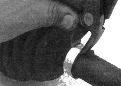
13.3a. Using diagonal nippers, cut the boot clamps (the small diameter clamp has a clamp lock: this…

13.3a. Using diagonal nippers, cut the boot clamps (the small diameter clamp has a clamp lock: this clamp can be cut using a hand-held power tool with a grinding disc; during assembly, a standard clamp should be installed, since a special device must be used to install a clamp with a clamp lock)
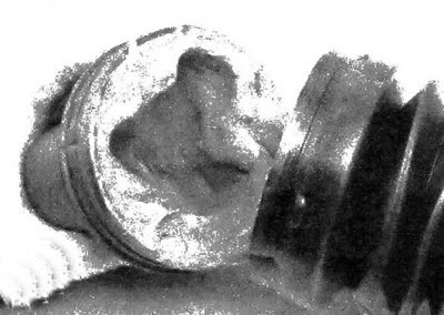


13.3b. Pull the housing off the tripod
13.3b. Pull the housing off the tripod


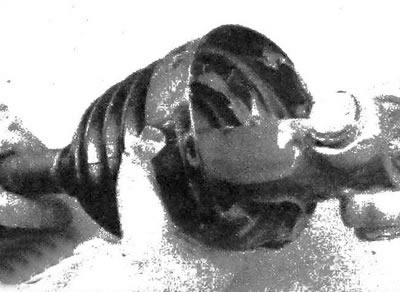
13.3s. Pull the boot towards the center of the drive shaft
13.3s. Pull the boot towards the center of the drive shaft


13.3d. Spread the ends of the retaining ring and pull it towards the center of the drive shaft

13.3d. Spread the ends of the retaining ring and pull it towards the center of the drive shaft
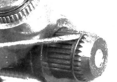

13.3e. Pull the tripod to open the locking ring; pry up and remove the ring
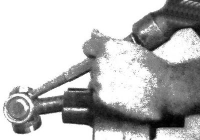
13.3e. Pull the tripod to open the locking ring; pry up and remove the ring


13.3f. Carefully knock the tripod off the drive shaft using a copper punch (do not hit it hard to…

13.3f. Carefully knock the tripod off the drive shaft using a copper punch (do not hit it hard to prevent the tripod from flying off, as this may cause the needle bearings to crumble
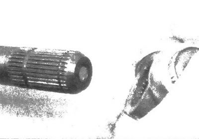

13.3g. When tightening the drive shaft tripod, it is necessary to hold the bearing with your hand…

13.3g. When tightening the drive shaft tripod, it is necessary to hold the bearing with your hand in its original position; it is preferable to tape the bearing to the tripod with adhesive or fabric tape
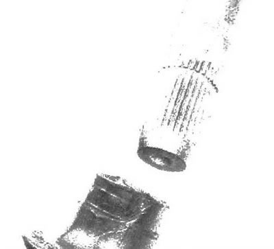

13.3h. Pull the boot off the drive shaft together with the retaining ring
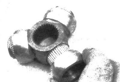
13.3h. Pull the boot off the drive shaft together with the retaining ring


13.3i Clean all old grease from the tripod and housing, then remove each bearing one at a time
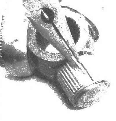
13.3i Clean all old grease from the tripod and housing, then remove each bearing one at a time


13.3j. Carefully disassemble each tripod section, clean the needle bearings in solvent and inspect…

13.3j. Carefully disassemble each tripod section, clean the needle bearings in solvent and inspect the rollers, tripod, bearings and pivot housing for material wear, signs of pitting and other defects
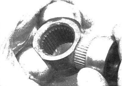

13.3k. Apply special grease to the inside of the bearings to glue the needle bearings, then slide…

13.3k. Apply special grease to the inside of the bearings to glue the needle bearings, then slide the outer races onto them
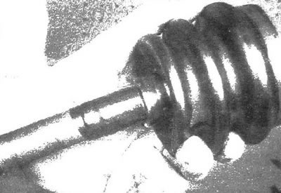


13.3l. Wrap the splines of the drive shaft with adhesive tape to prevent damage to the boot, then…

13.3l. Wrap the splines of the drive shaft with adhesive tape to prevent damage to the boot, then slide the smaller clamp and boot onto the drive shaft
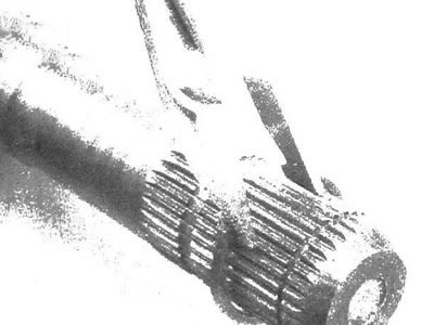

13.3m. Pull the tripod retaining ring onto the drive shaft, moving it past the mounting groove
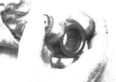
13.3m. Pull the tripod retaining ring onto the drive shaft, moving it past the mounting groove


13.3n. Install the tripod bearings by rotating the grooves in the countersunk hole towards the end…

13.3n. Install the tripod bearings by rotating the grooves in the countersunk hole towards the end of the shaft
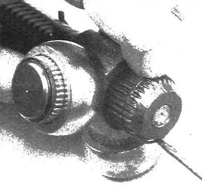


13.3. Install the retaining ring, then pull it towards the tripod and seat the ring in the groove
13.3. Install the retaining ring, then pull it towards the tripod and seat the ring in the groove


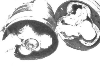
13.3p. Fill the hinge housing with half of the grease supplied with the repair kit, and place the…

13.3p. Fill the hinge housing with half of the grease supplied with the repair kit, and place the rest in the boot
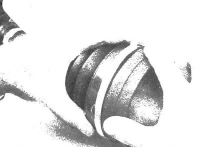

13.3q. Placing the clamp in its original location (without tightening it), install the tripod…

13.3q. Placing the clamp in its original location (without tightening it), install the tripod housing
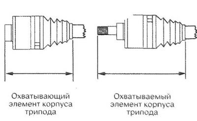

13.3r. Place the boot into the housing and into the groove of the drive shaft oil seal, then adjust…

13.3r. Place the boot into the housing and into the groove of the drive shaft oil seal, then adjust the length of the joint according to the specification data in this chapter
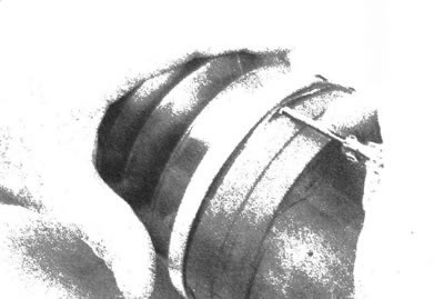

13.3s After adjusting the length of the hinge, insert a small screwdriver between the cover and the…

13.3s After adjusting the length of the hinge, insert a small screwdriver between the cover and the body to remove excess air (make sure that the cover is not deformed)...
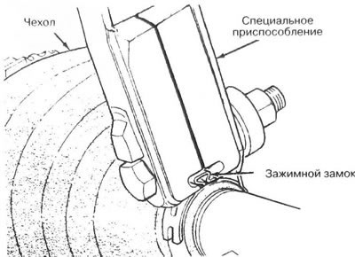

13.3t... then secure the clamp using a special tool (which is freely available)

13.3t... then secure the clamp using a special tool (which is freely available)


Outer CV joint


4. When replacing the outer CV joint boot, follow the accompanying illustrations (see illustrations 13.4a-13.4r).
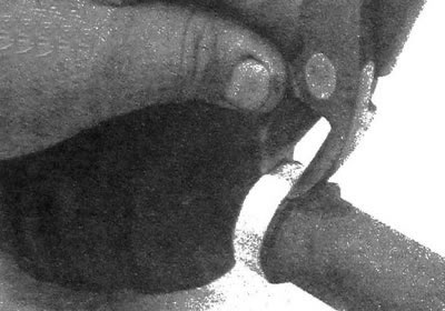
13.4a. Using diagonal nippers, cut the cover clamps (the small diameter clamp has a clamp lock;…

13.4a. Using diagonal nippers, cut the cover clamps (the small diameter clamp has a clamp lock; this clamp can be cut using a hand-held power tool with a grinding disc; during assembly, a standard clamp should be installed, since a special device must be used to install a clamp with a clamp lock)
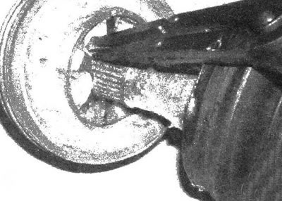

13.4b Spread the ends of the inner snap ring, then pull the CV joint off the drive shaft
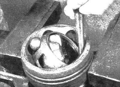
13.4b Spread the ends of the inner snap ring, then pull the CV joint off the drive shaft


13.4s. Press the inner race in sufficiently to remove, turn the race with your fingers, gently tap…

13.4s. Press the inner race in sufficiently to remove, turn the race with your fingers, gently tap it and the separator using a hammer and brass punch
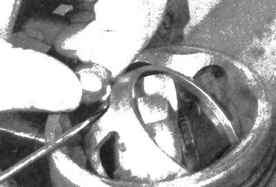

13.4d. Pry the balls out of the separator one by one
13.4d. Pry the balls out of the separator one by one


13.4e. Rotate the inner race and separator 90°, then align the separator windows (A) with the…

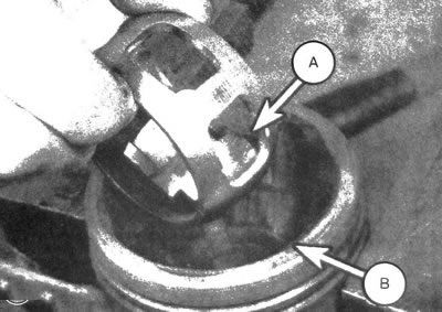
13.4e. Rotate the inner race and separator 90°, then align the separator windows (A) with the grooves in the housing (B) and, turning the inner race and separator upwards, remove the elements from the housing

13.4f. Align the grooves of the inner race with the windows of the separator, then turn the inner…

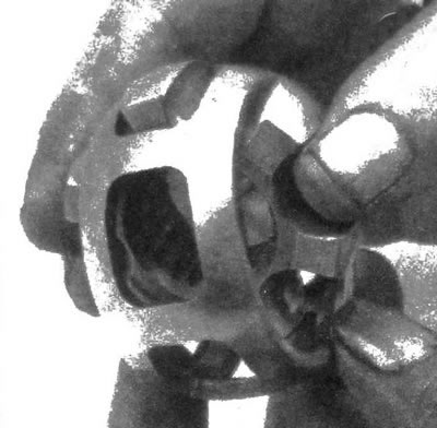
13.4f. Align the grooves of the inner race with the windows of the separator, then turn the inner race and remove it from the separator

13.4g. After cleaning the elements in solvent, inspect the grooves and depressions of the inner…

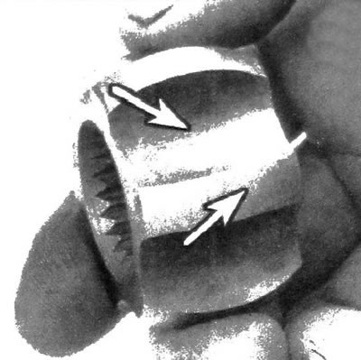
13.4g. After cleaning the elements in solvent, inspect the grooves and depressions of the inner race for signs of pitting and material wear

13.4h Inspect the separator for cracks, signs of pitting and material wear; the presence of…

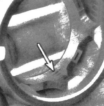
13.4h Inspect the separator for cracks, signs of pitting and material wear; the presence of polished spots on the working surfaces is not a defect
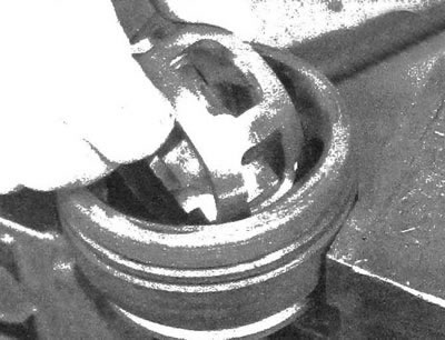

13.4i Rotate the inner race and separator 90°, then place the elements into the housing
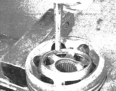
13.4i Rotate the inner race and separator 90°, then place the elements into the housing


13.4j. Turn the elements by gently striking them with a hammer and brass punch...
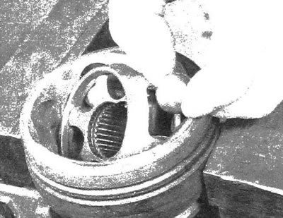
13.4j. Turn the elements by gently striking them with a hammer and brass punch...


13.4k...then press all the balls into the separator windows one by one
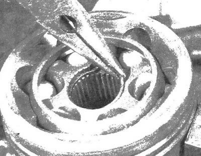
13.4k...then press all the balls into the separator windows one by one


13.4l. Using needle-nose pliers, place a new retaining ring into the groove...
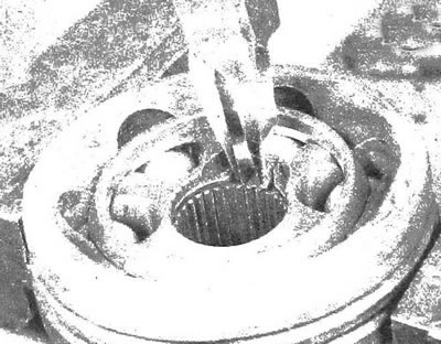
13.4l. Using needle-nose pliers, place a new retaining ring into the groove...


13.4m...then shrink the ring using special pliers
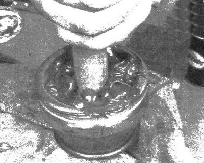
13.4m...then shrink the ring using special pliers


13.4n. Put grease into the spline hole of the hinge, then insert the wooden cylinder into it (the…

13.4n. Put grease into the spline hole of the hinge, then insert the wooden cylinder into it (the diameter of which is slightly smaller than the diameter of the drive shaft) and push the grease into the joint; perform the operation until the joint is filled with grease
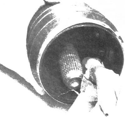

13.4o. Install the smaller clamp and boot onto the drive shaft, then pack the boot with grease...
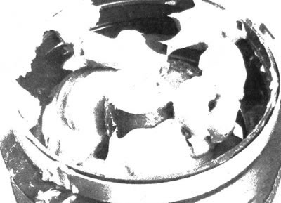
13.4o. Install the smaller clamp and boot onto the drive shaft, then pack the boot with grease...


13.4p....so that its level reaches the end of the drive shaft
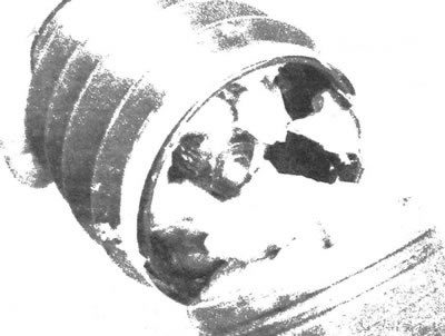
13.4p....so that its level reaches the end of the drive shaft


13.4q. Place the CV joint on the drive shaft, aligning the splines, then using a soft-faced hammer,…

13.4q. Place the CV joint on the drive shaft, aligning the splines, then using a soft-faced hammer, tap the joint onto the shaft until the retaining ring fits into the groove
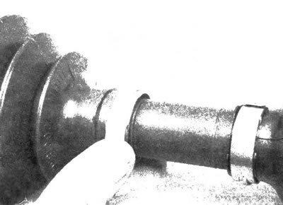

13.4r. Place the inner end of the cover into the groove and install the clamp, then do the same on…

13.4r. Place the inner end of the cover into the groove and install the clamp, then do the same on the other end of the cover; tighten the clamps using a special tool (see illustration 13.3t)


[Original version of the article on the website CHEVYMAN.RU]

The article was checked: Vladimir Romannikov
This article is available at russian, bulgarian, belarusian, ukrainian, serbian, croatian, romanian, polish, slovak, hungarian

Share information:

Previous articles
Trailblazer 1: Drive shafts and cardan
Next articles

Drive shaft (4WD models) — removal and installation
Drive shafts (4WD models) — general information and inspection
Bridge (rear) removal and installation
Differential gear seal — replacement
Axle shaft bearing (rear) — replacement
Front Axle Shift Drive (All Wheel Drive Models with Electric Shift Drive) — Replacement
Intermediate shaft bearing housing seals (4WD models) — replacement
Intermediate shaft bearing housing (4WD models) — removal and installation
Intermediate shaft (4WD models) — removal and installation
Front Differential Holder — Removal and Installation


See similar articles on the topic of Chevrolet cars:
Replacing the wheel drive shaft seal Chevrolet Aveo T250 (2006-2011)
Disassembling the intermediate drive shaft Chevrolet Captiva 1 (2006-2018)
Checking the accessory drive belt Chevrolet Cruze 1 (2008-2016)
Replacement of auxiliary drive belt Chevrolet Lacetti 1 (2002-2009)
Replacing the alternator drive belt Chevrolet Lanos T150 (2002-2009)
Oil pump drive shaft and gears Chevrolet Niva 1 (2002-2016)
Front axle shaft with housing (all-wheel drive models) — removal and installation Chevrolet Tahoe 1 (1992-2000)
Link in different formats to this page


Visitor comments

No comments yet


How much will 14 + 42 =


Orlando 1 (2010-2018) 
  • General information
  • Introduction to manual
  • User manual
  • Maintenance
  • Troubleshooting
  • Power unit
  • Engine repair
  • Fuel and control system
  • Cooling and lubrication system
  • Ignition system
  • Transmission
  • Clutch
  • Gearbox
  • Drive shafts
  • Chassis
  • Car suspension
  • Steering
  • Brake system
  • Body
  • Exterior (external elements)
  • Doors, locks and windows
  • Electrical equipment
  • Equipment and devices
  • Windscreen wipers
  • Power devices
  • Electrical diagrams


Trailblazer 1 (2001-2008) 
  • General information
  • User manual
  • Troubleshooting
  • Maintenance
  • Power unit
  • Engine in a car
  • Engine overhaul
  • Cooling and heating
  • Fuel and exhaust system
  • Engine electrical equipment
  • Engine control
  • Transmission
  • Automatic gearbox
  • Transfer case
  • Drive shafts and cardan
  • Chassis
  • Brake system
  • Car suspension
  • Steering
  • Body
  • Exterior (external elements)
  • Interior (internal elements)
  • Doors, locks and windows
  • Electrical equipment
  • Equipment and devices
  • Electrical circuits


Lumina 1 (1989-1994) 
  • General information
  • Maintenance
  • Power unit
  • Engine 3.1L V6
  • Engine 3.8L V6
  • Engine overhaul
  • Cooling system
  • Power and exhaust system
  • Fuel injection
  • Engine electrical equipment
  • Reduced exhaust gas toxicity
  • Transmission
  • Automatic gearbox
  • Drive shafts
  • Chassis
  • Brake system
  • Car suspension
  • Steering
  • Body
  • Heating and air conditioning
  • Repair of body elements
  • Doors, covers and windows
  • Interior (internal elements)
  • Electrical equipment
  • Equipment and devices
  • Electrical circuits


ChevyMan.ru © 2017-2026 · Mobile version · Feedback · Site search · Interesting to read · Sitemap: EN BG BY UA RS HR RO PL SK HU

Aveo 2003-2008 · Aveo 2006-2011 · Aveo 2012-2018 · Captiva 2006-2018 · Cruze 2008-2016 · Lacetti 2002-2009 · Lanos 2002-2009 · Niva 2002-2016 · Tahoe 1992-2000 · Tahoe 2000-2014 · Lumina 1 1989-1994 · Trailblazer 1 2001-2008 · Orlando 1 2010-2018 ·
🛡️ For your security and to improve our service, this site uses cookies. You can disable them in your browser.