
Contents: Removal ↧ Installation ↧
Removal
1. Loosen the wheel nuts, lift the car with a jack and install special supports. Remove the wheel.
2. Remove the protective panel located on the underside of the vehicle (see chapter 11).
3. Pry up and remove the hub cap (see illustration).
12.3. To knock the cap off the hub, you need to use a hammer and chisel
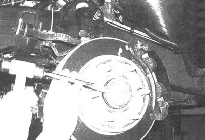
4. Remove the hub/drive shaft nut, which can be discarded after this. Wedge a tire iron between the wheel studs to prevent the hub from turning (see illustration). You can also lock the hub by inserting a long punch or screwdriver into the caliper window and inserting the tool into the disc cooling blades.
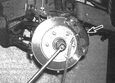
12.4. Wedge a tire iron between the wheel studs to prevent the hub from turning: you can also lock the hub by inserting a screwdriver through the window (marked with an arrow) and inserting the tool into the disk cooling blades
Warning: The hub nut is not re-installable. When installing the drive shaft, a new nut must be installed.
5. Disconnect the wheel speed sensor connector and release the wire from the holders. Remove the brake hose retainer bolt located at the junction of the metal brake pipe and the frame element (see chapter 9).
6. Remove the shock absorber (see chapter 10).
7. Remove the steering knuckle (see chapter 10), while pulling the drive shaft protrusion out of the hub.
Note: If the drive shaft protrusion is stuck in the hub, knock it out using a hammer and brass punch. If this does not disconnect the shaft, use a puller.
8. Using a hammer and brass punch, disconnect the inner end of the drive shaft from the differential or intermediate shaft. Place a punch against the inner CV joint housing of the drive shaft. Apply sufficient force to disengage the snap ring located on the inner end of the drive shaft from the differential or intermediate shaft. Disconnect the drive shaft from the differential.
Installation
9. Installation is carried out in the reverse order of removal, with the following steps.
10. Before installing the drive shaft, lubricate the outer spline with multi-purpose grease.
11. Install the new hub/drive shaft nut and tighten it to the specified torque.
12. Tighten the fasteners of the suspension elements to the torques given in chapter 10.
13. Tighten the wheel nuts to the torque value given in specifications of chapter 1.