


Contents: Removal and installation the… ↧ Removal and installation the "clock… ↧ Adjusting the "clock spring" ↧ Removal and installation the… ↧ Removal and installation of the… ↧ Removal and installation the side… ↧
Turn the steering wheel to the straight-ahead position. Turn the ignition switch to the LOCK position and remove the key. Remove the airbag fuse F8 in the instrument panel fuse box and wait for more than one minute for the airbag capacitor to discharge.
Removal and installation the driver's airbag module
Remove the two screws securing the driver's airbag module (during installation, the screws must be replaced).
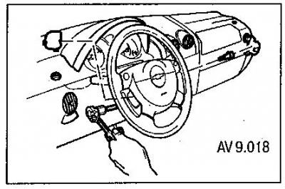
Disconnect the module connector.
Remove the airbag module from the steering wheel.
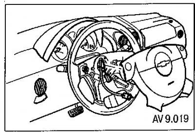
When installing, tighten the new screws to 8 Nm.
Removal and installation the "clock spring"
After removing the driver's airbag module, remove the steering wheel.
Remove the screws securing the upper and lower steering column covers.
Remove the lids.
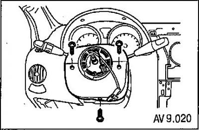
Disconnect the horn connector and the connectors at the bottom of the steering column.
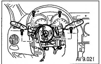
Remove the screws and the clock spring from the steering column (during installation, the screws must be replaced).
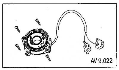
During installation, adjust the clock spring and tighten the new screws to 3 Nm.
Adjusting the "clock spring"
Set the steering gear to the straight-ahead position.
Turn the front wheels forward.
Turn the protrusion on the "clock spring" housing clockwise until it locks into place (don't put in too much effort!).
Align the marks (protrusions) on the body and on the moving part of the device. To do this, turn the clock spring mark counterclockwise, approximately three turns, until the neutral position of the moving part is reached (with the front wheels in a position corresponding to straight-line movement).
The marks on the spring parts must be aligned precisely.
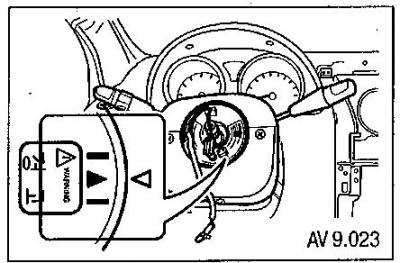
Note: Turning the clock spring (more than three turns clockwise or counterclockwise) may cause it to break.
Install the removed parts in reverse order.
Removal and installation the passenger airbag module
Remove the glove compartment.
Disconnect the yellow electrical connector.
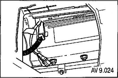
Loosen the screws securing the airbag module.
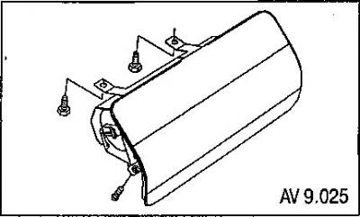
Remove the module.
When installing, tighten the mounting screws to a torque of 11 Nm.
Removal and installation of the indicator and diagnostic unit (IDU)
Remove the floor console.
Remove the shutter securing the BID connector.
Disconnect the electrical connector. Unscrew the mounting screws.
Remove the block.
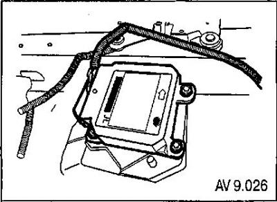
When installing, tighten the unit mounting screws to a torque of 10 Nm.
Removal and installation the side airbag sensor
Remove the center pillar trim.
Remove the side airbag sensor mounting screws.
Remove the side airbag sensor.
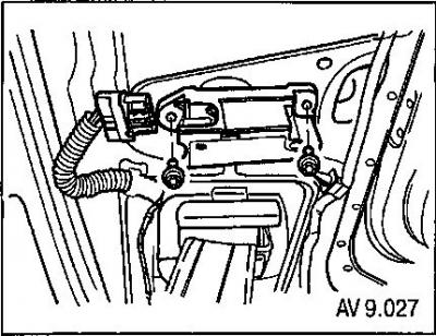
When installing, tighten the mounting screws to a torque of 8 Nm.