


Contents: Checking the Parking Assist System… ↧ Checking the functionality of the… ↧ Self-check of sensor serviceability ↧
Checking the Parking Assist System Warning Indicator
| Step | Operation | Values | Yes | No |
| 1 |
Is the lamp working?
|
-
|
Go to Step 3
|
Go to Step 2
|
| 2 |
Replace the warning indicator lamp.
|
-
|
-
|
-
|
| 3 |
Check the parking assist fuse F13 in the instrument panel fuse box.
Is fuse F13 blown?
|
-
|
Go to Step 4
|
Go to Step 5
|
| 4 |
|
-
|
-
|
-
|
| 5 |
Is the voltage within the specified range?
|
9 - 16 V
|
Go to Step 7
|
Go to Step 6
|
| 6 |
Eliminate the break in the power supply circuit to fuse F13.
|
-
|
-
|
-
|
| 7 |
Check the circuit between fuse F13 and the instrument cluster for an open or short to ground.
Has the cause been found and corrected?
|
-
|
The system is normal
|
Go to Step 8
|
| 8 |
Has the cause been found and corrected?
|
-
|
The system is normal
|
Go to Step 9
|
| 9 |
Check the circuit between ground and controller for an open circuit.
Has the cause been found and corrected?
|
-
|
The system is normal
|
Go to Step 10
|
| 10 |
Is the replacement complete?
|
-
|
-
|
Checking the functionality of the parking assistance system
Description of the scheme
The Parking Assist System informs the driver of a system malfunction via a warning indicator and an audible signal.
1. Determining a malfunction by a warning indicator
When the ignition is turned on for the first time, ignition voltage is supplied from fuse F18 in the instrument panel fuse block to input terminal 1 to detect the parking assist system (PAS) controller. In response, the PAS controller illuminates the warning indicator in the instrument cluster for 4 seconds and then extinguishes it while the controller performs a self-check of the PAS system. If the controller detects a malfunction in the system during this time, it commands the warning indicator to illuminate until the malfunction is corrected.
2. Determination of malfunction by sound signal
When the ignition is turned on, if the gearshift lever is moved to the "R" position, the PAS controller performs self-checking and turns on the buzzer. If there is no malfunction in the system, the controller emits a single buzzer sound lasting approximately 0.3 seconds.
When a fault is detected, the controller emits a series of 3 beeps 5 times, each lasting approximately 1.5 seconds.
Diagnostic recommendations
If the warning indicator illuminates due to a malfunction, perform the sensor self-test before performing the parking assist system function check. For how to perform the sensor self-test, refer to "Sensor self-test" in this section.
| Step | Operation | Values | Yes | No |
| 1 |
The indicator light stays on for 4 seconds and then goes out?
|
-
|
The system is normal
|
Go to Step 2
|
| 2 |
Set the gear shift lever to position R.
Does the parking assist controller sound the warning signal in normal parking assist alarm mode? (1 time for 0.3 seconds, then turn off)?
|
-
|
Go to Step 3
|
|
| 3 |
Perform a self-test of the sensor. See item "Self-check of sensor serviceability" in this section.
Has the cause been found and corrected?
|
-
|
Go to Step 1
|
Go to Step 4
|
| 4 |
Is the voltage approximately the stated value?
|
≈ 8 V
|
Go to Step 6
|
Go to Step 5
|
| 5 |
Has the cause been found and corrected?
|
-
|
Go to Step 13
|
Go to Step 7
|
| 6 |
Check the following circuits in the horn wiring connector for the following conditions:
Has the cause been found and corrected?
|
-
|
Go to Step 13
|
Go to Step 9
|
| 7 |
Has the cause been found and corrected?
|
-
|
Go to Step 13
|
Go to Step 8
|
| 8 |
Check for an open circuit in the ground circuit at the controller connector.
Has the cause been found and corrected?
|
-
|
Go to Step 13
|
Go to Step 12
|
| 9 |
Check the circuits between the BCM and the parking assist control module for an open or short to ground.
Has the cause been found and corrected?
|
-
|
Go to Step 13
|
Go to Step 10
|
| 10 |
Check the parking brake switch circuit for an open or short to ground.
Has the cause been found and corrected?
|
-
|
Go to Step 13
|
Go to Step 11
|
| 11 |
The indicator light stays on for 4 seconds and then goes out?
|
-
|
Go to Step 13
|
Go to Step 12
|
| 12 |
Is the replacement complete?
|
-
|
Go to Step 13
|
-
|
| 13 |
Operate the system to check if the problem has been corrected.
Has the cause been eliminated?
|
-
|
The system is normal
|
Go to Step 1
|
Self-check of sensor serviceability
Description of the scheme
If the warning light or buzzer indicates a malfunction, the sensor circuit must be diagnosed before the remaining parking assist circuits can be investigated. The parking assist control module can perform a health check for each rear obstacle sensor using the sensor health self-test mode. The following procedure describes the procedure to enter the sensor health check mode.
1. Turn on the ignition.
2. Turn the parking brake switch on/off 3 times, setting and releasing the parking brake 3 times within 10 seconds after turning the ignition on.
3. The controller will go into sensor health check mode.
Audible sensor error codes
If no faults are detected in the sensor circuit, the controller will emit a normal sound signal (1 time lasting 0.3 seconds).
If a fault is detected in the sensor circuit, an audible signal will be generated, the shape of which depends on the type of fault, as described below.
Left corner sensor
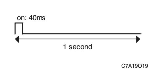
Left middle sensor
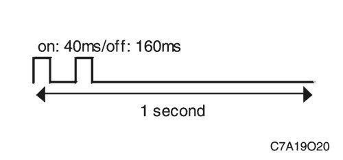
Right middle sensor
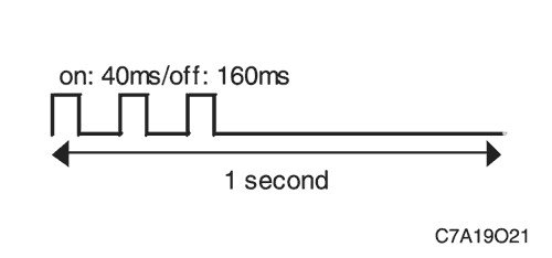
Right corner sensor
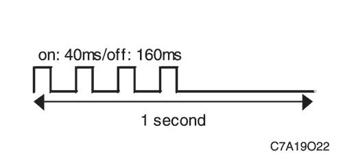
- 1 cycle lasts 3 seconds.
- The above sequence of sound signals is performed for 2 cycles.
- If a fault is detected in multiple sensors, the controller will repeat the beep code twice for all faulty sensors in the following order: left corner → left middle → right middle → right corner.
| Step | Operation | Values | Yes | No |
| 1 |
The indicator light stays on for 4 seconds and then goes out?
|
-
|
The system is normal
|
Go to Step 2
|
| 2 |
Is there a sound signal corresponding to normal operation? (only 1 time lasting 0.3 seconds)?
|
-
|
Go to Step 3
|
|
| 3 |
Determine which sensor circuit has a fault using the description of the sensor fault sound codes.
Has the sensor circuit suspected of having a fault been identified?
|
-
|
Go to Step 4
|
-
|
| 4 |
Check for poor contact at suspect sensors.
Has the cause been found and corrected?
|
-
|
Go to Step 11
|
Go to Step 5
|
| 5 |
Is the voltage approximately the stated value?
|
≈ 8 V
|
Go to Step 8
|
Go to Step 6
|
| 6 |
Has the cause been found and corrected?
|
-
|
Go to Step 11
|
Go to Step 7
|
| 7 |
Check for open or short circuit in low reference voltage circuit of suspect sensors.
Has the cause been found and corrected?
|
-
|
Go to Step 11
|
Go to Step 10
|
| 8 |
Check the parking assist controller for poor connections.
Has the cause been found and corrected?
|
-
|
Go to Step 11
|
Go to Step 9
|
| 9 |
Replace suspect rear obstacle sensors.
Replacement completed?
|
-
|
Go to Step 11
|
-
|
| 10 |
Is the replacement complete?
|
-
|
Go to Step 11
|
-
|
| 11 |
Operate the system to check if the problem has been corrected.
Has the cause been eliminated?
|
-
|
Go to Step 1
|
-
|
The article was reprinted from the website CHEVYMAN.RU