


Necessary equipment
- J-28585 Snap Ring Remover
- J-45186 Forward and Direct Drive Clutch Spring Compressor
- J-25024-A Clutch Spring/Booster Piston Compressor
- J-23327 Clutch Spring Compressor
1. Install the forward clutch piston (C1).
- Lubricate the new sealing rings with automatic transmission fluid and install them on the C1 piston.
- Lubricate the inner surface of the drum with automatic transmission fluid.
- Press piston C1 into the drum. Be careful not to damage the sealing rings.
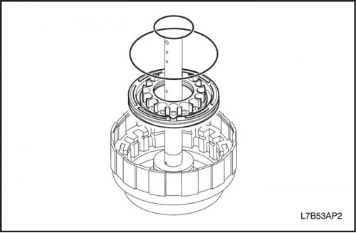
2. Install the direct drive clutch (C2).
- Lubricate the new sealing rings with automatic transmission fluid and install them on the piston.
- Lubricate the inner surface of piston C1 with automatic transmission fluid.
- Press the piston into piston C1.
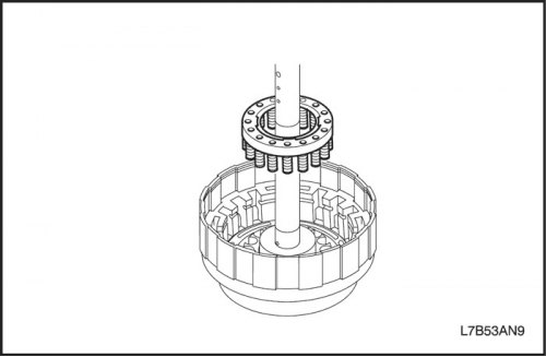
3. Install the return spring assembly.
- Install the return spring assembly into the direct drive clutch piston (C2).
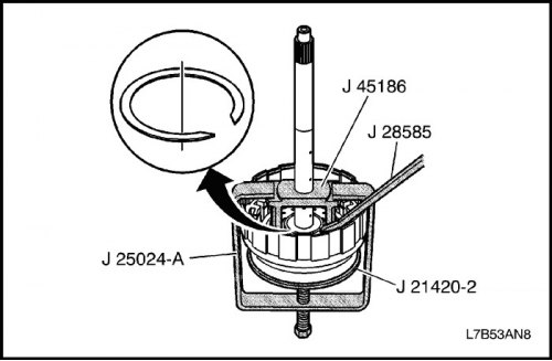
Important: Do not align the cut of the retaining ring with the locking protrusion of the spring.
- Place J-25024-A in a vise with the clamp bolt down and pulled back.
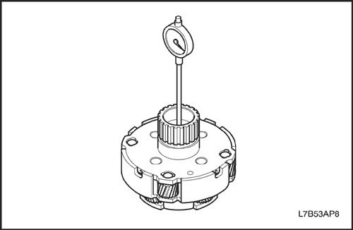
- Install J-45186 to the direct/forward clutch housing shaft and input shaft assembly.
- Place J-21420-2 from J-23327 on top of J-24024-A jack bolt.
- Use the pressure bolt to compress the clutch spring so that the retaining ring can be installed.
- Using J-28585 or snap ring pliers, install snap ring.
- Remove the tools.
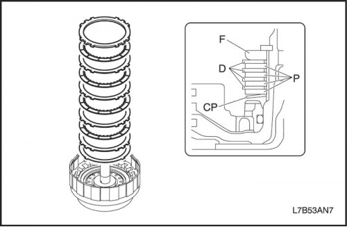
4. Install the flange, disc, plate and flexible disc of the direct drive clutch (C2).
- Install the elastic disc.
Important: Make sure the elastic disc is in the correct direction.
- Install the flange, discs and plates as shown in the figure.
Important: Make sure that the number and order of installation of the flange and discs and plates is correct.
- Order: F - D - P - D - P - D - P - D - P - UD
|
Clutch and brake
|
Flange (F)
|
Plate (P)
|
Disk (D)
|
Elastic disk (ED)
|
|
Direct Drive Clutch (C2)
|
1
|
4
|
4
|
1
|
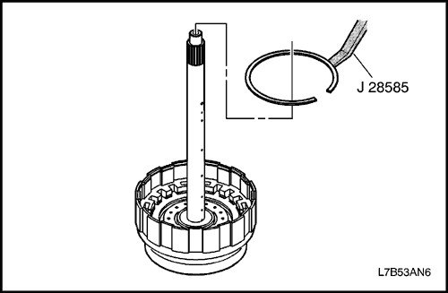
- Using J-28585, install the retaining ring into the groove. Make sure the cut of the retaining ring does not align with any of the notches.
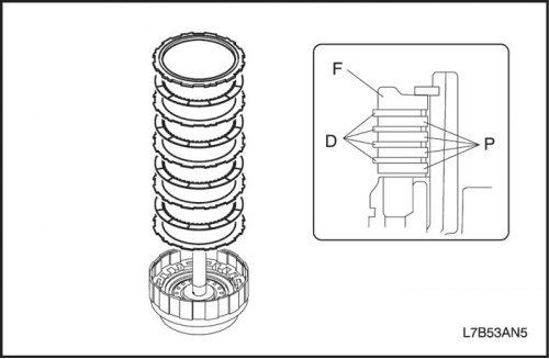
5. Install the direct drive clutch flange, disc and plate (C1).
- Install the flange, discs and plates as shown in the figure.
Important: Make sure that the number and order of installation of the flange and discs and plates is correct.
- Order: F - D - P - D - P - D - P - D - P
|
Clutch and brake
|
Flange (F)
|
Plate (P)
|
Disk (D)
|
|
Forward clutch (C1)
|
1
|
4
|
4
|
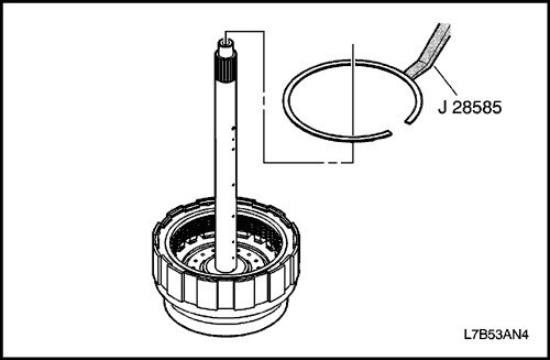
- Using J-28585, install the retaining ring into the groove. Make sure the cut of the retaining ring does not align with any of the notches.
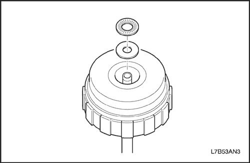
6. Install the seal ring, thrust bearing and race.
- Install the thrust bearing and race.
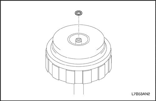
- Lubricate the new sealing ring with automatic transmission fluid and install it into the groove of the primary shaft assembly.
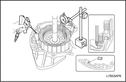
Caution: When working with compressed air, wear protective glasses to prevent eye injury.
7. Check the piston stroke of the direct drive clutch (C2).
- Install the primary shaft assembly into the rear crankcase and position the indicator as shown in the figure.
- Apply compressed air (4 kg/cm?) and measure the piston stroke C2.
- Piston stroke: 1.49-1.91 mm (0.059-0.075 inches)
If the piston stroke C2 is not within the norm, select another flange.
- Flange thickness type: 4.0mm (0.157 inches), 4.2 mm (0.165 inches), 4.4 mm (0.173 inches)
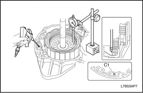
Caution: When working with compressed air, wear protective glasses to prevent eye injury.
8. Check the forward clutch piston stroke (C1).
- Install the primary shaft assembly into the rear crankcase and position the indicator as shown in the figure.
- Apply compressed air (4 kg/cm?) and measure the piston stroke C1.
- Piston stroke: 0.71-1.09 mm (0.028-0.043 inches)
If the piston stroke C1 is not within the norm, select another flange.
- Flange thickness type: 5.0mm (0.197 inches), 5.2 mm (0.205 inches), 5.4 mm (0.213 inches)
The article is based on data from the website «chevyman.ru»