ChevyMan.ru
Mazda Mitsubishi Toyota Land Rover Honda Kia Nissan
English Русский
Български
Беларускі
Український
Српски
Hrvatski
Română
Polski
Slovenský
Magyar
|
Articles | Sitemap | Contacts |


Home   Aveo   Captiva   Cruze   Lacetti   Lanos   Niva   Tahoe   Others  
Tahoe 2 and 3 (2000-2014) Tahoe 1 (1992-2000)
  • Home
  • Tahoe
  • 2 (2000-2014)
  • Transmission
  • Automatic gearbox 4L60, 4L65, 4L70
  • Valve body and pressure switch

Valve body and pressure switch (Chevrolet Tahoe 2)

            0

Contents: Removal ↧ Installation ↧

Removal


1. Before you begin removing the valve body, make sure that it is really necessary.

2. Without removing the valve body, you can replace:
  • torque converter clutch valve (1);
  • pressure regulating valve (2);
  • internal wiring harness (3);
  • 2-3 gear shift valve (4);
  • 1-2 gear shift valve (5);
  • pressure regulator valve position sensor (6);
  • 3-2 gear shift valve (7);
  • torque converter clutch pulse width modulation valve (8).
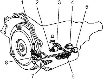
torque converter clutch pulse width modulation valve (8).


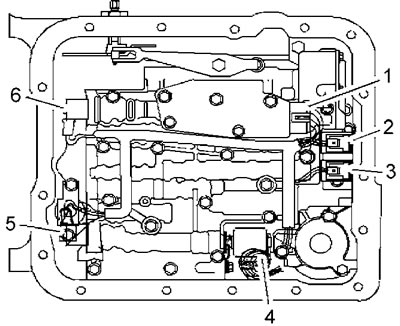
3. Disconnect the internal connectors:
  • pressure regulator valve position sensor (1);
  • 1-2 gear shift valves (2);
  • 2-3 gear shift valve (3);
  • pressure regulating valves (4);
  • clutch pulse width modulation valve (5);
  • 3-2 gear shift valve (6).

3-2 gear shift valve (6).


4. (Modifications) Loosen the bolt (2) of the working fluid indicator limiter bracket.
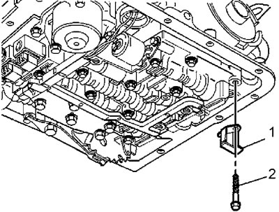


4. (Modifications) Loosen the bolt (2) of the working fluid indicator limiter bracket.


5. Remove the working fluid indicator limiter bracket (1).

6. Using a small screwdriver, remove the retainer (2) of the torque converter clutch pulse width modulation valve (1). If necessary, turn the valve in its seat to gain access to the retainer.
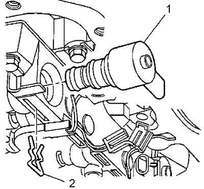
6. Using a small screwdriver, remove the retainer (2) of the torque converter clutch pulse width…


7. Remove the torque converter clutch pulse width modulation valve (1).

8. Loosen the torque converter clutch locking valve mounting bolts.
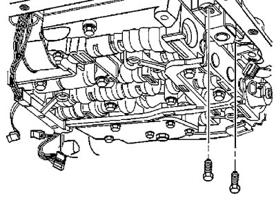
8. Loosen the torque converter clutch locking valve mounting bolts.


9. Remove the torque converter clutch lock-up valve from the valve body (together with a sealing ring and a bundle of wires).
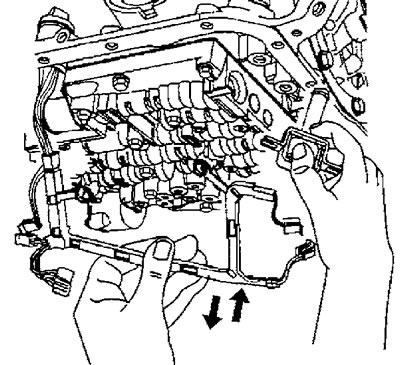


9. Remove the torque converter clutch lock-up valve from the valve body (together with a sealing…


10. Place the wires aside.

11. Loosen the bolts securing the pressure switch to the valve body.
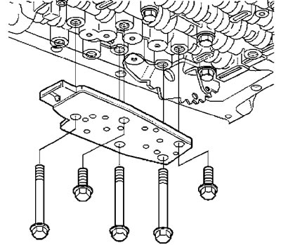
11. Loosen the bolts securing the pressure switch to the valve body.


12. Remove the pressure switch.

13. Check the condition of the switch.
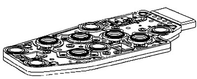
13. Check the condition of the switch.


14. Loosen the manual lock spring mounting bolt.
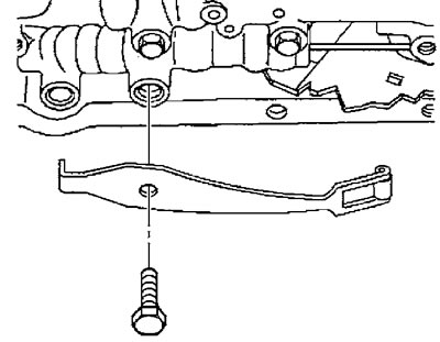
14. Loosen the manual lock spring mounting bolt.


15. Remove the retainer spring.


16. Check the condition of the retainer, look for cracks or damage.

Caution: When removing the valve body, keep it horizontal to prevent loss of the check valve balls located in the valve body holes.


17. Unscrew the remaining valve body mounting bolts.

18. Carefully lower the valve body while simultaneously disconnecting the manual valve rod.
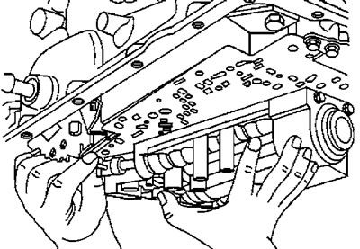
18. Carefully lower the valve body while simultaneously disconnecting the manual valve rod.


19. Remove the 7 check valve balls.
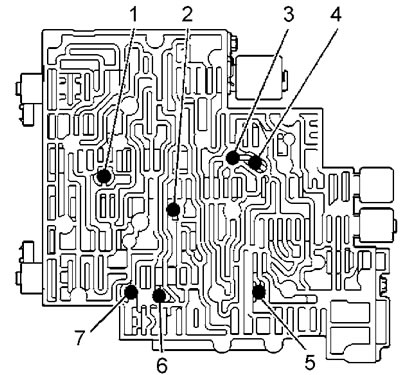
19. Remove the 7 check valve balls.


20. Unscrew the bolts (58) and (59) of the battery cover (57).

21. Remove the cover (57).
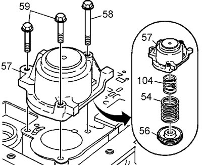
21. Remove the cover (57).


22. Unscrew the bolts (77) of the spacer.


23. Remove the spacer (53).
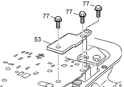
23. Remove the spacer (53).


24. Remove the valve body gasket (52), spacer (48), and crankcase gasket (47).
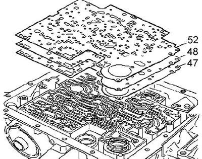
24. Remove the valve body gasket (52), spacer (48), and crankcase gasket (47).


Installation


1. Install a NEW valve body gasket (52), spacer (48) and a NEW crankcase gasket (47).

2. Install the spacer (53) and the spacer mounting bolts (77). Tighten the bolts. Tightening torque 10 Nm.

3. Install the battery cover assembly (57).

4. Install bolts (58) and (59). Tighten the bolts. Tightening torque 10 Nm.

5. Place seven check valve balls into the valve body.

6. Carefully install the valve body while connecting the manual valve rod.

7. Make sure that the rod (3) of the manual valve is engaged with the valve (2) and the locking lever (1).
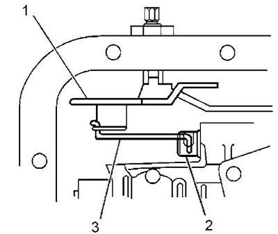
7. Make sure that the rod (3) of the manual valve is engaged with the valve (2) and the locking…


8. Install one bolt (M6x1 length 47.5 mm) into the central hole (1) of the valve body, tighten the bolt by hand.
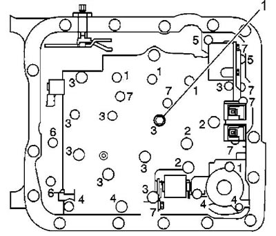


8. Install one bolt (M6x1 length 47.5 mm) into the central hole (1) of the valve body, tighten the…


Note: Since the valve body mounting bolts are different sizes, please be careful when installing them.


9. Install, but do not tighten, the valve body mounting bolts. The bolt locations are shown in the figure.
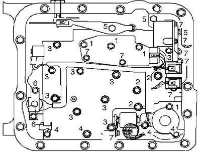
Locations of valve body mounting bolts. 1 - M6x1-65.0 mm, 2-M6x1-54.4 mm, 3-M6x1-47.5 mm,…

Locations of valve body mounting bolts. 1 - M6x1-65.0 mm, 2-M6x1-54.4 mm, 3-M6x1-47.5 mm, 4-M6x1-35.0 mm, 5-M8x1-20.0 mm, 6-M6x1-12.0 mm, 7-M6x1-18.0 mm.


Note: (modifications) do not install the fluid level indicator limiter bracket and its mounting bolt yet.


10. Install the manual lock spring.

11. Install the manual lock spring mounting bolt.

12. Set the liquid pressure switch.

13. Tighten the switch mounting bolts by hand.

Note: The valve body mounting bolts are tightened in a "spiral" pattern starting from the center. Any other tightening pattern may result in incorrect valve operation.


14. Tighten the valve body mounting bolts in a spiral pattern. Tightening torque 11 N·m.
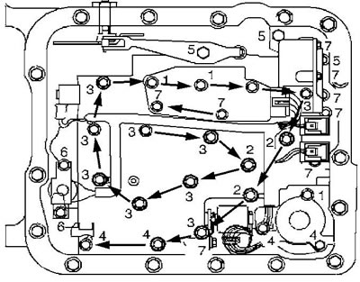
14. Tighten the valve body mounting bolts in a spiral pattern. Tightening torque 11 N·m.


15. Make sure that the manual lock spring is correctly positioned on the lock lever. Tighten the mounting bolt. Tightening torque 11 N·m.

16. Install the TCC lockup valve with a NEW O-ring onto the valve body.

17. Install the locking valve mounting bolts and tighten the bolts. Tightening torque 11 Nm.

18. Install the inner wire bundle onto the valve body. The bundle casing has a protrusion (1). The orientation of the bundle is shown in the figure.
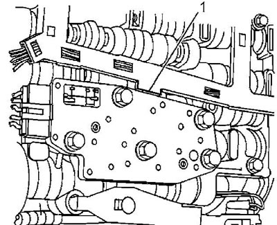
18. Install the inner wire bundle onto the valve body. The bundle casing has a protrusion (1). The…


19. Place the casing projection between the valve body and the pressure switch at location (2). Press the casing of the wire bundle into the bosses (1) and (3) until it is fully secured.
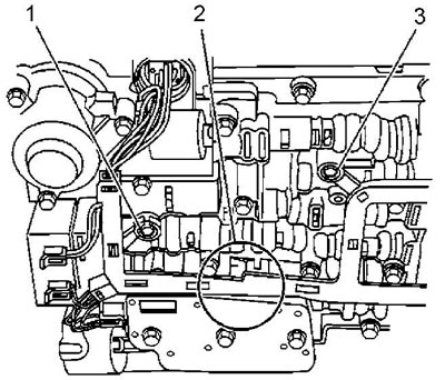
19. Place the casing projection between the valve body and the pressure switch at location (2).…


20. Install the torque converter clutch pulse width modulation valve.

21. Install the modulation valve retainer.

22. (Modifications) Install the working fluid indicator limiter bracket. Tighten the mounting bolts. Tightening torque 11 N·m.

23. Connect all connectors:
  • pressure regulator valve position sensor
  • 1-2 gear shift valve
  • 2-3 gear shift valve
  • pressure regulating valves
  • clutch pulse width modulation valve
  • 3-2 gear shift valve.

24. Install the automatic transmission filter.

[The article was reprinted from the website CHEVYMAN]

The article was checked: Vladimir Romannikov
This article is available at russian, bulgarian, belarusian, ukrainian, serbian, croatian, romanian, polish, slovak, hungarian

Share information:

Previous articles
Tahoe 2 and 3: Automatic gearbox 4L60, 4L65, 4L70
Next articles

Pressure regulator — removal and installation
Vehicle speed sensor
Engine start inhibit switch
Automatic transmission control cable — adjustment
Automatic transmission control cable — removal and installation
Automatic transmission rear housing
Control and switching valves


See similar articles on the topic of Chevrolet cars:
Oil pressure dropped Chevrolet Aveo T300 (2012-2018)
Airbag: Switch Chevrolet Captiva 1 (2006-2018)
Oil pressure dropped Chevrolet Cruze 1 (2008-2016)
Removal camshafts and hydraulic valve lifters Chevrolet Lacetti 1 (2002-2009)
Ignition switch (lock) Chevrolet Lanos T150 (2002-2009)
Ignition switch Chevrolet Niva 1 (2002-2016)
Removal and installation the oil filter flange and pressure regulator valve Chevrolet Lumina 1 (1989-1994)
Link in different formats to this page


Visitor comments

No comments yet


How much will 46 + 42 =


Tahoe 2 and 3 (2000-2014) 
  • General information
  • Vehicle characteristics
  • Vehicle device
  • Manual
  • Maintenance
  • Power unit
  • Engine repair
  • Engine overhaul
  • Cooling system
  • Injection and control system
  • Exhaust system
  • Engine electrical equipment
  • Transmission
  • Automatic gearbox 4L60, 4L65, 4L70
  • Automatic gearbox 6L50, 6L80, 6L90
  • Transfer case
  • Drive shafts and cardan
  • Front drive axle
  • Rear drive axle
  • Chassis
  • Car suspension
  • Steering
  • Brake system
  • Body (until 2007)
  • Exterior (external elements)
  • Interior (internal elements)
  • Doors, locks and windows
  • Heating and air conditioning
  • Security System (SRS)
  • Body (since 2007)
  • Exterior (external elements)
  • Doors, locks and windows
  • Interior (internal elements)
  • Electrical equipment
  • Electrical appliances (until 2007)
  • Lighting and lamps (until 2007)
  • Audio system (until 2007)
  • Electrical appliances (since 2007)
  • Lighting and lamps (since 2007)
  • Audio system (since 2007)
  • Wiring diagrams (2000-2005)
  • Wiring diagrams (2005-2007)
  • Wiring diagrams (since 2007)


Tahoe 1 (1992-2000) 
  • General information
  • User manual
  • Maintenance
  • Power unit
  • Engine in a car
  • Engine removed
  • Cooling system
  • Heating and air conditioning
  • Fuel and exhaust systems
  • Decreased toxicity
  • Transmission
  • Manual gearbox
  • Automatic gearbox
  • Transfer case
  • Clutch and drive shafts
  • Chassis
  • Brake system
  • Car suspension
  • Steering
  • Body
  • Repair of body elements
  • Electrical equipment
  • Engine electrics
  • Equipment and devices
  • Electrical circuits


ChevyMan.ru © 2017-2026 · Mobile version · Feedback · Site search · Interesting to read · Sitemap: EN BG BY UA RS HR RO PL SK HU

Aveo 2003-2008 · Aveo 2006-2011 · Aveo 2012-2018 · Captiva 2006-2018 · Cruze 2008-2016 · Lacetti 2002-2009 · Lanos 2002-2009 · Niva 2002-2016 · Tahoe 1992-2000 · Tahoe 2000-2014 · Lumina 1 1989-1994 · Trailblazer 1 2001-2008 · Orlando 1 2010-2018 ·
🛡️ For your security and to improve our service, this site uses cookies. You can disable them in your browser.