
Contents: Removal ↧ Installation ↧
Warning: Dust generated by wear of the pads is hazardous to health. Do not blow it off with compressed air or inhale dust. When servicing the brake system, it is recommended to wear a protective mask or respirator. Do not use gasoline or solvents for cleaning. Use only a special product for cleaning brake system components.
Note: the hub with the bearing is a non-separable element, which is replaced entirely if one of the elements is damaged.
Removal
1. Loosen the front wheel mounting nuts, lift the vehicle and place it on vertical supports. Remove the wheel.
2. If performing the procedure on a 4WD vehicle, remove the hub cap and, using a socket head and a long lever, loosen the nut of the applicable shaft/hub (see chapter 8). Insert a large pry bar between the two wheel studs or insert a large screwdriver through the center of the caliper and the rotor cooling blades to hold the hub still while loosening the hub nut.
3. Remove the caliper and hang it on a piece of wire, then remove the caliper bracket (see chapter 9). Pull the disc off the hub.
4. Remove the wheel speed sensor from the hub (see illustration).
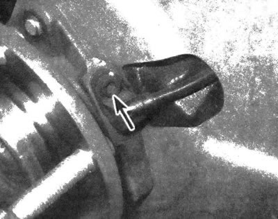
8.4 The wheel speed sensor is attached to the hub with a single screw, unscrew the screw and pull the sensor out in a perpendicular direction (don't pick on him)
5. Performing the procedure from the back side of the steering knuckle, unscrew the hub mounting bolts from it (see illustration). Remove the disc shield.
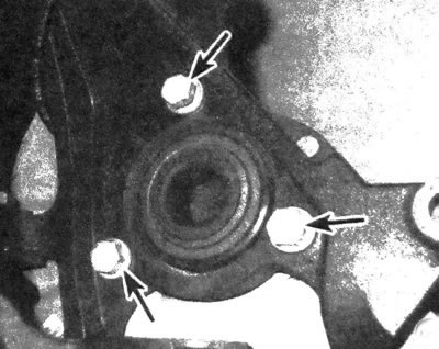
8.5. Remove the hub/bearing mounting bolts from the steering knuckle
6. Remove the hub from the steering knuckle. When performing the procedure on a four-wheel drive vehicle, it is necessary to pull the assembly off the drive shaft splines.
Caution: Do not allow the drive shaft to be pulled out, as this will cause the inner CV joint components to separate.
If you have difficulty disconnecting, place a two-jaw puller on the hub flange and pull the drive shaft spline out of the hub. The hub should come off the steering knuckle, but if it doesn't, loosen it by lightly tapping it in different directions.
Installation
7. Clean the mating surfaces on the steering knuckle, bearing flange and knuckle groove.
8. Insert the hub together with the bearing into the steering knuckle. On a four-wheel drive model, it is also necessary to insert a half shaft into it.
Note: Before installing the hub on a four-wheel drive vehicle, it is necessary to lubricate the axle shaft splines with a universal grease.
Install the disc shield and tighten its mounting bolts to the required torque.
9. Insert the wheel speed sensor into the hub hole and tighten the mounting bolt to the torque specified in the specifications in Chapter 9.
10. Install the disc, bracket and caliper (see chapter 9).
11. On a four-wheel drive model, install the nut and tighten it to the torque specified in chapter 8 specifications. Insert a large screwdriver through the center of the caliper and disc cooling blades to hold the hub still while tightening its nut. Install the cap.
12. Install the wheel, lower the vehicle onto a supporting surface and tighten the wheel nuts to the torque specified in specifications of chapter 1.
The article was reprinted from the website CHEVYMAN