
Warning: The models described are equipped with air bags. Before performing procedures in the area where the passive restraint components are located, it is necessary to turn off the power supply to the SRS system to prevent accidental deployment of the airbags, which could result in serious injury (see chapter 12).
Note: This procedure applies to the front heater fan and its electrical circuit on all models described. Some vehicles are equipped with additional heating and air conditioning systems for the rear compartment. It is not possible to diagnose these systems using conventional universal devices. If necessary, such vehicles should be sent to a company or other station with the appropriate level of qualification, since in this case, diagnostics of a system with a built-in control unit is carried out using special electronic equipment.
1. Inspect the fuse contacts (with HVAC marking) and all electrical circuit connectors for the presence of corrosion deposits, as well as for the reliability of the connection. Make sure the battery charge level is sufficient.
Note: The heater/fan relay is located in the motor housing, which is located in the passenger compartment. The fuse labeled HVAC is located in the box located on the left side of the instrument panel.
2. Shift the transmission into Park, set the parking brake and turn the ignition key to Run. There is no need to start the engine.
3. Remove the central heating/air conditioning unit cover located under the glove box, then remove the box.
4. Connect a voltmeter to the terminals of the heater fan motor (see illustration).
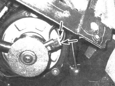
9.4 Connect a voltmeter to the heater fan motor terminals and cycle the speed switch through all positions
5. Move the fan switch through all positions, noting the change in the voltmeter reading. The change in voltage indicates that the fan speed switch is working.
6. If the fan does not turn on despite the presence of voltage in the circuit, check its functionality. Disconnect the wires from the motor and connect it directly to the ground circuit (chassis element) and the battery (via a connecting wire that has a fuse). If the fan does not turn on, it is broken.
7. If no voltage was supplied to the electric motor, but the fan was tested and found to be operational, follow the path of its ground wire, which has a connection in the area of the right front corner of the lower console. Make sure that the ground wire is securely connected to the vehicle body element. If necessary, restore the ground loop circuit.
8. If the fan does not function again after this, inspect the resistor, control panel and associated wiring. The malfunction may be caused by failure or disruption of contacts of these elements.