
Contents: Checking the degree of contamination… ↧ Refrigerant charging ↧ Heating system ↧ Eliminating the characteristic… ↧ Automatic heating/air conditioning… ↧
Warning: The air conditioning system is under high pressure. Do not loosen the couplings or remove components without first discharging the system when contacting an authorized or specialized service station. When disconnecting the air conditioning system couplings, wear protective glasses or a mask.
Caution 1: The air conditioning systems of the vehicles described in this manual use R-134a refrigerant, which is not an environmentally harmful product. The components of the system filled with this refrigerant, as well as compressor oil of the corresponding type, must not be exposed to the refrigerant R-12. Mixing the two types of refrigerant is fraught with damage to the system components.
Caution 2: When replacing air conditioning system components, add compressor oil in a volume equal to the amount of oil remaining in the removed component. Before adding oil to the system, it is necessary to study the instructions to ensure its compatibility with the R-134a refrigerant.
1. To ensure and maintain the efficiency of the air conditioning system, the following procedures should be performed during regular maintenance.
- a) Inspect the compressor drive belt. Replace it if necessary (see chapter 1).
- b) Check and, if necessary, adjust the drive belt tension to the standard (see chapter 1).
- c) Inspect the system hoses for cracks, swelling, hardening and other signs of wear. Make sure that there is no oil leakage through the hoses and couplings. If the above signs are detected, make the necessary replacement of the hoses.
- d) Inspect the condenser fins for trapped leaves, insect debris or other debris. Clean the plates using compressed air and a soft brush.
- e) Make sure the system is properly charged with refrigerant.
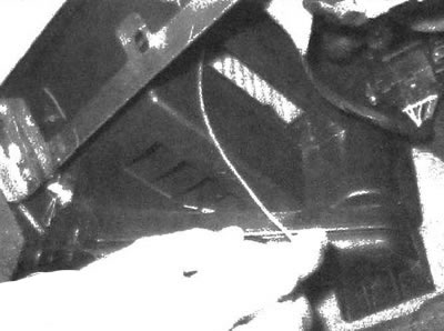
- f) If there is a characteristic water noise behind the instrument panel, or if water leaks are found on the interior carpet, make sure that the evaporator casing drain pipe has sufficient permeability (see illustration). To check, insert a piece of wire into the tube.
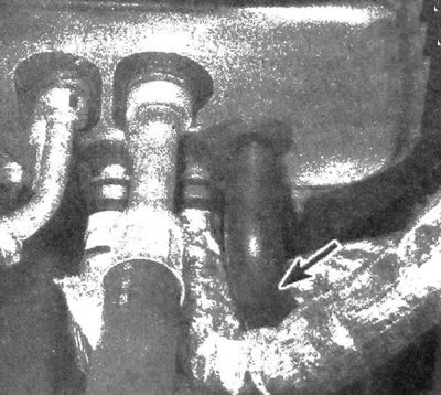
13.1. Make sure that the evaporator casing drain pipe located on the rear bulkhead of the engine compartment is not restricted. This angle was obtained by pointing the lens from above the engine
2. It is strongly recommended to turn on the air conditioning system at least once a month for at least 10 minutes. This is especially important in winter, as long-term inactivity of the system can cause irreversible hardening of the internal seals of the system. It should be noted that the air conditioner compressor is switched on in the "Defrost" mode (defrosting glass).
3. If you detect any problems with the air conditioning system, you must continue the procedure, starting with the operations described in paragraph. 6, and perform the check described below.
4. Due to the complexity of the system design, as well as the need to use special equipment, diagnostics should be entrusted to a professional specialist with the appropriate qualifications. Therefore, this manual does not include descriptions of disassembly and repair procedures - they must be performed at a specialized station. A car mechanic only needs to check the functionality of the drive clutch and determine the degree of contamination of the system with refrigerant. This chapter provides descriptions of simple checks as well as procedures for replacing components.
5. There is only one reason for a system's reduced efficiency that can be identified and corrected by a home mechanic - a lack of refrigerant. If the system's performance has decreased due to refrigerant leakage, perform one of the following check procedures to determine the cause.
Checking the degree of contamination of the system with refrigerant
6. Warm up the engine to normal operating temperature.
7. Set the air conditioning control to the minimum temperature position and the fan switch to the maximum speed position. Open the doors (to prevent the air conditioning system from turning off immediately after cooling the air in the cabin).
8. Once the engine has reached operating temperature, feel the coolant lines that are connected to the evaporator on the rear bulkhead of the engine compartment.
9. The tube going from the accumulator to the evaporator should be cold, and the outlet line of the evaporator (tubes through which the refrigerant returns to the compressor) have a slightly higher temperature (10-15°C warmer). If the evaporator outlet line is significantly warmer than the inlet line, or if the evaporator inlet line is not cold, the system needs to be recharged with refrigerant. Place the thermometer on the central air vent grille of the instrument panel and turn on the air conditioning system at maximum efficiency. The temperature of the air coming out of the deflector should be 2-5°C lower than the ambient temperature (up to 5°C). If the ambient temperature is extremely high (around 45°C), the air coming out of the air duct may also have a relatively high temperature (around 16°C), but as a rule, the air conditioning temperature is 2-5°C lower than the temperature outside the car.
10. If the air is not cooled sufficiently, the system probably needs to be refilled.
11. If the air remains warm and the system does not operate, check that the compressor drive clutch is working properly.
12. With an assistant turning on the air conditioning system, inspect the front of the compressor. The coupling should click and its center portion should begin to rotate. If this does not happen, turn off the engine and disconnect the low pressure circuit sensor of the system (see illustration 13.22). Short-circuit the connector contacts with the connecting wire and turn on the air conditioning system again. If this triggers, the pressure in the system is too high or too low. Contact a branded or specialised station to diagnose the system.
13. If the clutch does not engage, inspect the corresponding fuse. Inspect the fuses located in the indoor unit.
14. Remove the compressor clutch relay (A/C) from the panel located in the engine compartment for testing (chapter 12). With the relay removed and the ignition on, make sure that voltage is supplied to the two relay terminals. When the ignition is on, power must be supplied to the contact terminals of the relay power circuit, as well as the control circuit.
15. Using an additional wire, connect the contacts of the relay power circuit, located in the block, to the contact of the wire leading to the compressor drive clutch (to determine which terminals need to be connected, check the color and location of the wires in the electrical diagrams). When the contacts are connected, a clicking sound from the drive clutch should be heard. If the clutch does not click, disconnect its connector from the compressor and make sure that voltage is supplied to it from the battery. Ensure there is continuity between the compressor clutch ground and the black terminal on the connector. If the clutch does not operate, and the power and grounding circuits are in good condition, then the fault lies directly in the compressor clutch.
16. If the compressor clutch does not operate when the system is turned on, while the clutch, relay and electrical circuits are in good condition and the system is fully charged with refrigerant, contact a company or other specialized station to diagnose the PCM electronic unit and examine the corresponding electronic circuits.
17. Carrying out a more detailed inspection and more in-depth diagnostics are beyond the capabilities of an amateur mechanic.
Refrigerant charging
Caution: When recharging or replacing elements, use refrigerant, oil and seals that comply with the R-134a grade. Seals and compressor oil used in combination with conventional R-12 refrigerant are not compatible with the described air conditioning systems.
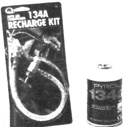
18. Purchase the appropriate R-134a refrigerant refill kit from your local auto parts store (see illustration). The kit consists of a 400-gram can of R-134a refrigerant, a threaded nipple and a short hose that connects to the threaded nipple and the air conditioning system service valve located in the low-pressure circuit. Since one can of refrigerant may not be enough to completely charge the system, it is a good idea to purchase an extra can.
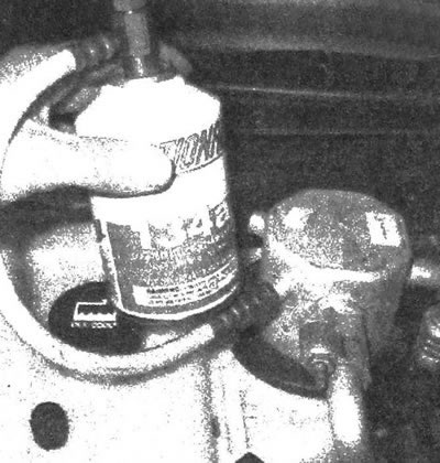
13.18. Coolant (available for sale in auto shops) is charged into the low pressure circuit using a simple
Warning: Do not add more than two cans of refrigerant to the system.
19. Connect the system priming kit according to the instructions supplied with it.
Warning: Do not connect the kit to a high pressure circuit. The kit nipple can only be connected to the low pressure circuit.
20. Unscrew the valve of the fitting included in the kit and screw the fitting onto the can of refrigerant, having first made sure that the sealing ring or rubber gasket on the threaded part of the fitting has not been displaced from its original position.
Warning: When handling cans containing refrigerant under high pressure, wear protective glasses or a mask.
21. Remove the dust cap from the service valve connector located in the low pressure circuit of the air conditioning system and connect the quick-disconnect hose connector supplied in the kit to the valve (see illustration).
13.21. Connect the kit to the low pressure located on the accumulator marking
22. Warm up the engine to normal operating temperature and turn on the air conditioning system. Do not allow the hose to come into contact with the fan blades or other moving parts of the engine.
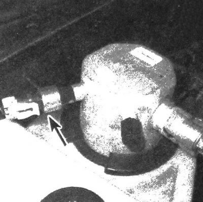
13.22. The low pressure circuit switch of the air conditioning system is located on the battery. If the compressor drive clutch does not engage when filling the system, disconnect the connector and short the terminals (on the wiring harness) connecting wire
Note 1: Refrigerant charging is performed with the compressor running. If the clutch is in the off cycle, turn the air conditioner switch to the maximum efficiency position and leave the vehicle doors open to keep the clutch in the on cycle.
Note 2: If the compressor clutch does not engage when charging refrigerant, pull out the plug of the low pressure circuit switch and short-circuit the connector terminals with a straightened paper clip or a bypass wire (see illustration).
23. Screw in the valve of the fitting to pierce the membrane of the can with the pin containing the refrigerant, then unscrew the valve again to release the refrigerant. You should be able to hear the hissing sound of the escaping gas. When filling the system through the low pressure circuit, keep the can in a vertical position, shaking it periodically. Refueling should be carried out with breaks necessary to stabilize the temperature in the system.
Note: If you wrap the jar with a towel soaked in hot water, which will prevent the jar from icing up, the filling process will speed up.
24. Install a thermometer on the central air vent of the instrument panel and use it to monitor the temperature of the air supplied to the passenger compartment. If the system is fully charged with refrigerant, the thermometer should display about 5°C. If the ambient temperature is extremely high (about 45°C), the air coming from the deflector may also have a relatively high temperature (about 16°C), but, as a rule, the air coming from the system into the cabin is cooler than the outside air by about 2-5°C.
25. When the can is empty, close the valve on the fitting and disconnect the hose from the service valve of the low pressure circuit. Replace the dust cap.
26. Disconnect the hose from the can. Store the kit with the valve closed to prevent accidental rupture of the refrigerant can membrane during the next refill.
Heating system
27. Moisture on the mat under the heater, as well as the smell of antifreeze spreading from the deflectors (or the steam coming out of it) are signs of a leak in the heater heat exchanger. In this case, you will have to remove it (see subsection 12) and install a new element (most specialized workshops do not repair leaking heater heat exchangers).
28. The heating system may not operate efficiently for the following reasons.
- a) The thermostat is stuck in the open position, which prevents the coolant circulating in the heater from heating up sufficiently. Replace the thermostat (see subsection 3).
- b) Insufficient permeability of the heater hose, which limits the circulation of the coolant. Feel both heater hoses that enter the engine compartment bulkhead. They should be hot. If one of the hoses does not heat up, it means that the hose or heater flow is limited, or the heater valve is closed. Disconnect the hoses and flush the heater by directing a reverse flow of water from a garden hose into it. If the heater is not clogged but circulation is not occurring properly, remove the hoses and flush them with clean water.
- c) If the heater's throughput is reduced and this problem is not solved by flushing, the heat exchanger should be replaced (see subsection 12).
Eliminating the characteristic unpleasant odor from the air conditioning system
29. The formation of an unpleasant odor in the air conditioning system ducts is a consequence of the growth of fungus on the surface of the evaporator. A warm, humid environment is ideal for mold growth.
30. Access to the evaporator on most models is very difficult. Service and repair stations require a lengthy and expensive mold removal procedure, during which the evaporator casing is opened and the mold is completely removed using powerful chemicals. You can remove mold from your air conditioning system yourself, but this will require special chemicals that are much more powerful than regular household detergents and deodorants.
31. Automotive stores offer a wide range of aerosol products for disinfecting car air conditioning systems, but it should be noted that the price and effectiveness of the product are directly dependent. The procedure should begin by running the air conditioning system for ten minutes in the recirculation mode ("RECIRC") at the highest fan speed. You should also set the air conditioning temperature to maximum to dry out the system and disconnect the clutch connector to prevent the compressor from shutting off during the procedure (see subsection 15).
32. The disinfectant usually comes in an aerosol can with a long hose. Remove the lower instrument panel trim panel located on the passenger side, then remove the small service cover located on the HVAC unit housing (heater/air conditioner). Insert the tip into the hole and move it to the left, towards the evaporator heat exchanger, and spray the product according to the accompanying instructions (see illustration). Try to apply the product to the entire surface of the evaporator, directing the spray from the aerosol up, down and to the sides. The duration of spraying and the intervals between spraying should be in accordance with the instructions of the disinfectant manufacturer.
13.32 Spray the antiseptic onto the evaporator heat exchanger. Cover the area to be sprayed with plastic wrap or a cloth mat
33. After cleaning the evaporator, the best way to prevent mold from appearing is to periodically check the drain tube for patency (see illustration 13.1).
Automatic heating/air conditioning system
34. Some of the vehicles described are equipped with an automatic climate control system as an option. This system has a separate control unit, which receives impulses from various sensors of the heating and air conditioning systems. As with the engine management system, this system also has a self-diagnosis function, which allows you to determine the causes of possible malfunctions. Repairing components and restoring the functionality of the automatic climate control system is beyond the capabilities of an amateur mechanic. If any problems occur, please contact a branded or specialized station.
[The original text can be found on the website: chevyman]