
- Battery cable terminals are free of deposits and are securely tightened to the terminals.
- The battery cables are in good condition (see subsection 4). Replace the wires if necessary.
- The battery passes all tests (see subsection 3). Replace the battery if necessary.
- The starter wiring and connectors are in good condition.
- The starter bolts are securely tightened.
- The fuses in the engine compartment block are not blown (see chapter 12). If a fuse is found to be blown, determine and correct the cause, then replace it.
- The functionality of the ignition switch electrical circuit is confirmed (see chapter 12).
- Starter relay is operational (it is located in the fuse box, relay, which is located in the engine compartment). The procedure for checking the relay's functionality is described in chapter 12.
- The PARK/NEUTRAL selector position sensor is operational (see chapter 7). The functionality of this system is ensured by the supply of power from the battery to the starter relay.
2. If, despite the above conditions, the starter does not turn on from the ignition switch, check the voltage supplied from the battery to the solenoid valve. This test will determine if the valve is receiving sufficient voltage from the ignition switch. Connect a test lamp or voltmeter to the solenoid valve terminal, then have an assistant turn the ignition switch to the "START" position. If no voltage is detected in the circuit after this, inspect the ignition switch, wiring, all fuses and relays of the starting system (see the electrical diagrams provided in chapter 12). If the test detects the presence of voltage, but the electric motor does not turn on, it is necessary to remove (see subsection 13) and place the starter on the workbench to perform its testing (see subsection 4).
3. If the starter shaft rotates slowly, it is necessary to check the starting voltage of the electric motor and determine the current drop in the starter-battery circuit. This test is carried out with the starter installed on the vehicle. Turn on the starter for about ten seconds (or less). Measure the battery voltage while cranking. The voltage should be at least 8.5 V. Also determine the current drop using an ammeter. This value should not exceed 350 A. If the current drop exceeds the set limit, contact the authorized service station for starter diagnostics. A number of factors influence the starting torque potential of a starter. The battery must be in good working order and its parameters must not be reduced. Make sure that the battery condition has been checked thoroughly. The battery terminals must be securely tightened. There should be no corrosion deposits on the contact leads and terminals. If the test is performed at low ambient temperatures, the battery and/or engine must be pre-warmed.
4. If the starter is receiving power but the rotor is not turning, remove the traction solenoid from the starter mounted on the workbench. The solenoid valve is probably out of order. Less common is the seizure of an electric motor. To rule out this cause, try turning the crankshaft pulley before performing the following steps. Secure the starter with the solenoid valve in a bench vice and connect the wire connected to the positive pole to the starter terminal marked "B+". Connect the other wire connected to the negative terminal of the battery to the starter housing (see illustration). Install the starter switch and apply battery voltage to the solenoid terminal marked S (do not apply voltage for more than 10 seconds). In this case, the solenoid rod, lever and clutch should extend, after which the gear will rotate. If the drive extends but the pinion does not rotate, the solenoid is OK and the starter motor is faulty. If the solenoid valve clicks but does not move, then the solenoid and/or starter is faulty. If, after applying voltage, the drive extends and the gear rotates, then the starter/solenoid valve is in working order.
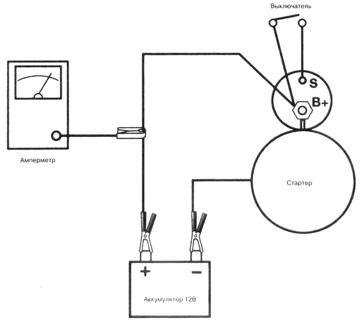
12.4. Scheme of testing the removed starter