
Warning 1: When working on ignition components, extreme caution must be taken as this system generates extremely high voltages which may be present not only at the coil and spark plug contacts but also at the contacts of other components and devices included in the system circuit.
Warning 2: The following procedures require the engine crankshaft to be rotated. Do not allow connecting wires, loose clothing, long hair, etc. to come into contact with moving parts of the engine (drive belt, cooling fan, etc.).
1. Before concluding that the ignition system in a vehicle whose engine does not start is faulty, it is necessary to perform a number of initial checks.
- a) Make sure the battery cable terminals are tight and free of deposits.
- b) Check the battery performance (see subsection 3). Replace the battery if necessary.
- c) Inspect the wires and connectors at the coil connections and the ignition system control unit.
- d) Inspect the corresponding fuses located in the distribution block, which is located in the engine compartment (see chapter 12). If it turns out that the fuse has blown, replace it, having first eliminated the cause of the blown fuse.
2. If the engine rotates and does not start, or if there is a noticeable misfire, make sure that sufficient secondary voltage is supplied to the spark plugs to produce a spark.
3. Disconnect the fuel system by removing the fuel pump relay located in the engine compartment distribution block (see chapter 12).
4. Disconnect the coil (see subsection 7) from one of the spark plugs and connect a special system tester to the protective cover connector (which can be purchased at most auto stores). Connect the tester via its clamp to a bolt or metal bracket on the engine (see illustration). Turn the crankshaft and look at the tester tip. A bright blue spark should form at the tip. The presence of a weak or uneven spark means the same thing as its absence.
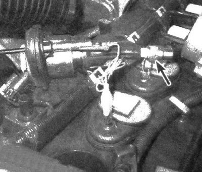
6.4 To check using a tester, you need to disconnect the coil and connect the device to the connector in the spark plug boot, and also connect the tester to the ground point. Turn the crankshaft, if sufficient voltage is generated in the circuit, then a spark will jump between the spark plug electrodes and the tester body (the presence of a weak or irregular spark means the same as its absence)
5. The presence of a spark indicates that sufficient voltage is being supplied to the spark plugs to ignite the mixture. Repeat the above procedure on the remaining cylinders to ensure that the coil and control systems are working properly and that the spark plug boots are in good condition. If the ignition system is in good working order, then the cause of the problem may be mechanical in nature or be a consequence of a malfunction of the fuel system components. It should be noted that spark plugs may not pass a spark due to contamination. Remove and inspect them as described in chapter 1, or make a replacement.
6. If no spark is detected on any of the cylinders, inspect the PCM I fuse located in the engine compartment distribution block.
7. If no spark is detected on one or more cylinders, disconnect the ignition coil connector and check for battery voltage at terminal "A" with the ignition key in the ON position. Repair the circuit that is not receiving power, if necessary.
8. If the engine does not start due to lack of spark or misfiring, check the ignition system for proper operation according to the engine type as follows.
Warning: The following procedure requires the engine crankshaft to be rotated. When operating the starter, do not allow loose clothing, long hair, etc. to come into contact with the drive belt and cooling fan, as this may result in serious injury.
9. Make sure that voltage from the battery is supplied to the coils through the ignition switch. Connect the electrode of a twelve-volt test lamp to the negative terminal of the battery. Disconnect the connector from one of the ignition coils and check for voltage at the pink terminal of the connector. Power is supplied when the ignition switch is in the ON position. If no power is detected, examine the circuit between the engine compartment distribution block and the coil connector. Also inspect the fuses. Make sure there is continuity to the ground loop that is connected to the black terminal of the coil connector. If it is determined that the coil is receiving voltage, but it does not generate a spark, then the cause of the malfunction should be sought directly in the coil, the crankshaft position sensor, the PCM control unit, or in the wiring.
10. Make sure that the PCM is sending an excitation signal to the coil. Connect one electrode of the test lamp to the positive terminal of the battery and connect the other electrode to the control circuit terminal (this contact pin is the central one in the connector). Turn the crankshaft. If the control circuit is operational, the rotation of the crankshaft should be accompanied by flashes of the lamp. If necessary, perform the described test on each coil. If it is determined that the coil is receiving an excitation signal and the power and ground circuits are good, but no spark is produced, replace the coil. If the coil does not receive an excitation signal, check the functionality of the crankshaft position sensor (see chapter 6). If the sensor is found to be OK, examine the circuit sections that connect the coil to the PCM. If the circuits are confirmed to be OK, contact an authorized service center to have the PCM diagnosed.
The article was borrowed from the website «CHEVYMAN.RU»