
ChevyMan.ru
Mazda Mitsubishi Toyota Land Rover Honda Kia Nissan
English Русский
Български
Беларускі
Український
Српски
Hrvatski
Română
Polski
Slovenský
Magyar
|
Articles | Sitemap | Contacts |


Home   Aveo   Captiva   Cruze   Lacetti   Lanos   Niva   Tahoe   Others  
Cruze 1 (2008-2016)
  • Home
  • Cruze
  • J300 (2008-2016)
  • Body
  • Heating and air conditioning
  • Replacing the drive pulley bearing

Replacing the drive pulley bearing (Chevrolet Cruze J300)

            0

The pulley has a double-row ball bearing that does not require adjustment or lubrication during operation. When pressing out, the bearing is destroyed, so press it out only for replacement.

You will need: a 14 mm wrench, a special puller for removing the pressure plate, a three-jaw puller for removing the compressor pulley, a snap ring puller, a press or a device for pressing out bearings.

1. Remove the refrigerant from the air conditioning system (see "Removal refrigerant from the air conditioning system") and disconnect the wire from the negative terminal of the battery.

2. Remove the compressor (see "Removal and installation the air conditioning compressor").
2. Remove the compressor (see «Removal and installation the air conditioning compressor»).


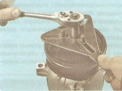
3. While holding the pressure plate from turning, unscrew the fastening nut.
3. While holding the pressure plate from turning, unscrew the fastening nut.


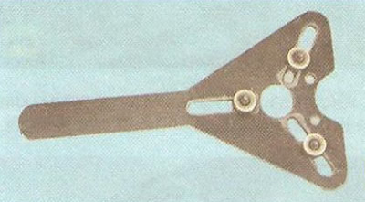
Note: Use a special device to hold the compressor pressure plate from turning.


Note: Use a special device to hold the compressor pressure plate from turning.


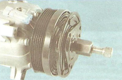
4, Install a special thread puller and press the pressure plate off the compressor shaft.

Helpful Hint: The pressure plate is mounted on the shaft with tension, so do not try to remove it by inserting a screwdriver into the gap between the pulley and the plate. This will cause the plate to deform and will require replacement.

Helpful Hint: The pressure plate is mounted on the shaft with tension, so do not try to remove it…


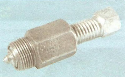
To remove the pressure plate, use a special thread puller.
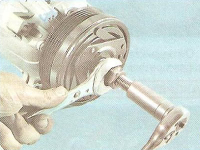

To remove the pressure plate, use a special thread puller.


Screw the puller sleeve into the threaded hole of the pressure plate hub and, by turning the stop screw of the puller, press the plate.
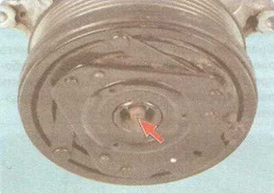


Screw the puller sleeve into the threaded hole of the pressure plate hub and, by turning the stop…


During operation, the thread in the hub hole may become clogged with dirt and rust. In this case, clean the thread before screwing in the puller sleeve.
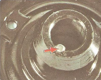

During operation, the thread in the hub hole may become clogged with dirt and rust. In this case,…


5. Inspect the key and keyway of the pressure plate. If the keyway is worn, replace the plate.
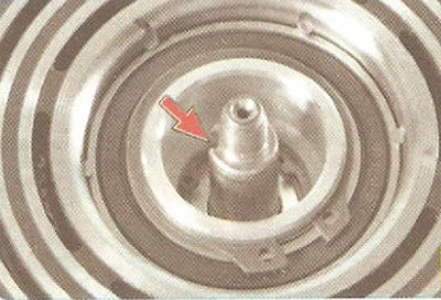
5. Inspect the key and keyway of the pressure plate. If the keyway is worn, replace the plate.


6. Inspect the shaft seal surface. If there are signs of oil leakage through the shaft seal, the compressor must be replaced.


Helpful Hint: In some cases, if a leak is detected, the seal can be replaced. However, it should be remembered that the leak is usually caused by shaft play due to wear of the support bearings, corrosion or wear of the shaft surface in the seal contact area. Therefore, replacing the seal will only provide a short-term result at best. If a seal leak is detected, we recommend replacing the compressor assembly.
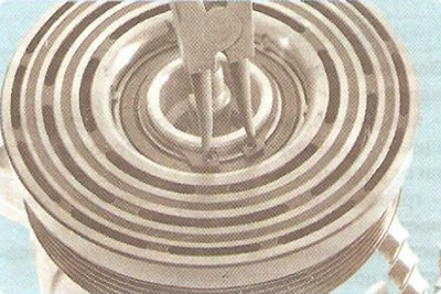

Helpful Hint: In some cases, if a leak is detected, the seal can be replaced. However, it should be…


7. Using a special puller, remove the pulley bearing retaining ring.
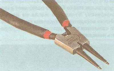
7. Using a special puller, remove the pulley bearing retaining ring.


Note: Use a special snap ring puller to remove the snap ring.

Note: Use a special snap ring puller to remove the snap ring.


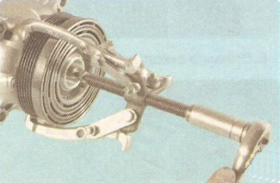
8. Install the puller and press the pulley off the compressor front cover mounting journal.


8. Install the puller and press the pulley off the compressor front cover mounting journal.


Warning: To avoid damaging the shaft threaded end when installing the puller, screw the old pressure plate mounting nut onto it a few turns.
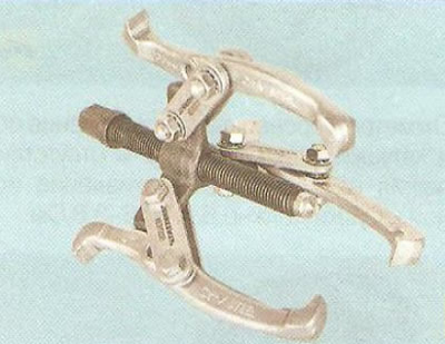

Warning: To avoid damaging the shaft threaded end when installing the puller, screw the old…


Helpful Hint: A universal three-jaw puller is useful for removing the pulley.
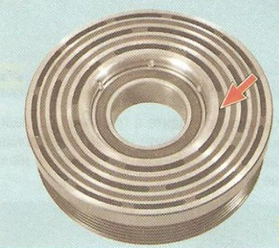

Helpful Hint: A universal three-jaw puller is useful for removing the pulley.


9. Inspect the friction working surfaces of the pulley...
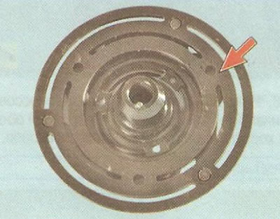
9. Inspect the friction working surfaces of the pulley...


10. ...and the pressure plate, paying attention to the presence of deep ring marks, scoring, obvious signs of wear and overheating. If necessary, replace defective parts.
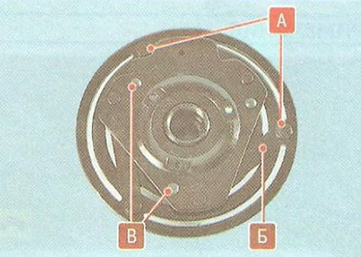


10. ...and the pressure plate, paying attention to the presence of deep ring marks, scoring,…


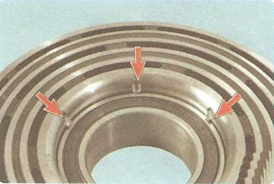
11. Inspect the rivet joints A and B, the elastic steel leashes B of the plate. If the leashes are broken or the rivet joints are loose, replace the pressure plate.
11. Inspect the rivet joints A and B, the elastic steel leashes B of the plate. If the leashes are…


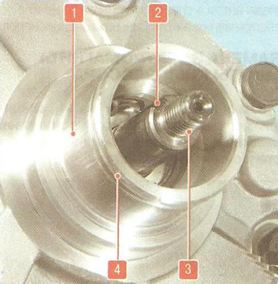
12. After removing the pulley, inspect the keyway 2 and threaded end 3 of the shaft, groove 4 for the retaining ring and the seating surface 1 of the cover neck (for clarity, the magnet coil has been removed). If they are worn out or damaged, the compressor must be replaced.
12. After removing the pulley, inspect the keyway 2 and threaded end 3 of the shaft, groove 4 for…


13. On a lathe, cut off the crimps that secure the bearing to the pulley.
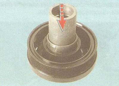
13. On a lathe, cut off the crimps that secure the bearing to the pulley.


14. Using a mandrel of suitable diameter, press the old bearing out of the pulley.
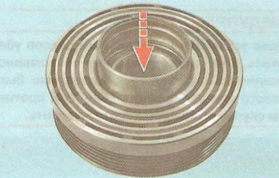
14. Using a mandrel of suitable diameter, press the old bearing out of the pulley.


15. Press in the new bearing. When pressing in, apply force only to the outer race of the bearing. The outer race from the old bearing can be used as a mandrel.

16. After pressing in, secure the bearing by punching the edge of the pulley mounting hole.

Warning: Be extremely careful when pressing the bearing.
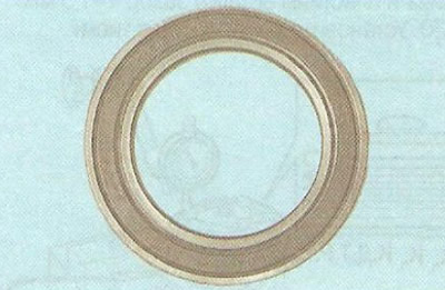

Warning: Be extremely careful when pressing the bearing.


The outer race of the pulley bearing has a very thin wall. Even a slight misalignment can cause the bearing to fail. After pressing, check the condition of the bearing. It should rotate evenly, silently, without jamming. There should be no axial or radial play.
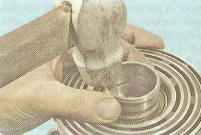

The outer race of the pulley bearing has a very thin wall. Even a slight misalignment can cause the…


17. Press the pulley onto the compressor front cover. When pressing, apply force only to the inner race of the bearing. You can use the inner race from the old bearing as a mandrel.

18. Install the retaining ring. Make sure the ring is fully seated in the groove.
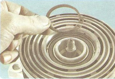
18. Install the retaining ring. Make sure the ring is fully seated in the groove.


Warning: After installing the pulley on the compressor, make sure that the pulley rotates smoothly, quietly, without jamming. There should be no axial or radial runout. Otherwise, the pulley must be replaced.
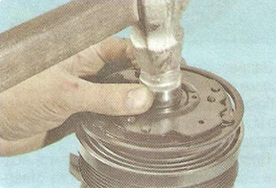

Warning: After installing the pulley on the compressor, make sure that the pulley rotates smoothly,…


19. Place the pressure plate on the shaft, aligning the key and keyways on the shaft and plate hub. Press the plate onto the shaft so that there is a gap of 1-1.5 mm between the friction surfaces of the pulley and the plate.

20. Place the compressor in a vice.
20. Place the compressor in a vice.


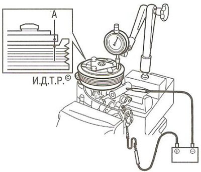
21. Install the dial indicator as shown in the figure. Connect the positive terminal of the battery to the coil winding connector and the negative terminal to the compressor body. Measure the gap A between the friction surfaces of the pressure plate and the pulley (the gap is equal to the measured difference in size between the positions of the pressure plate with the compressor clutch engaged and disengaged) every 60° around the circumference. If the gap is not the same at different points around the circumference, the pressure plate is deformed and must be replaced. The nominal gap should be 0.35-0.85 mm. If the gap is larger, press the hub onto the shaft. If smaller, press the hub off the shaft with a puller.
21. Install the dial indicator as shown in the figure. Connect the positive terminal of the battery…


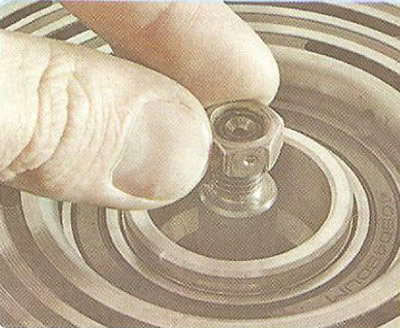
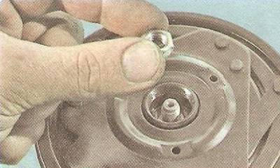
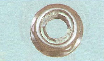
22. After completing the adjustment, screw on the new lock nut and tighten it to a torque of 5 Nm.
22. After completing the adjustment, screw on the new lock nut and tighten it to a torque of 5 Nm.


Note: Use a special disposable lock nut to secure the pressure plate.


23. Install the compressor and all removed parts in the reverse order of removal.

24. Fill the air conditioning system with refrigerant at a specialized center for servicing automotive air conditioners.

(The article is based on data from the website: CHEVYMAN.ru)

The article was checked: Vladimir Romannikov
This article is available at russian, bulgarian, belarusian, ukrainian, serbian, croatian, romanian, polish, slovak, hungarian

Share information:

Previous articles
Cruze 1: Heating and air conditioning
Next articles

Removal and installation the air conditioning compressor
Removal and installation the air conditioning compressor pressure regulator
Features of air conditioning compressor operation
Replacing the sealing rings
Removal refrigerant from the air conditioning system
Replacing the compressor clutch solenoid
Replacing the condenser
Replacing the filter element of the receiver-dryer
Replacing the thermostatic valve
Replacing the pressure sensor


See similar articles on the topic of Chevrolet cars:
Replacing the clutch release drive slave cylinder with the clutch release bearing Chevrolet Aveo T300 (2012-2018)
Idle pulley of the auxiliary drive belt Chevrolet Captiva 1 (2006-2018)
Replacing the auxiliary drive belt tensioner roller Chevrolet Lacetti 1 (2002-2009)
Replacing the alternator drive belt Chevrolet Lanos T150 (2002-2009)
Clutch release hydraulic drive Chevrolet Niva 1 (2002-2016)
Checking, adjusting and replacing drive belts of attachments Chevrolet Tahoe 1 (1992-2000)
Removal, replacing the protective cover and installing the inner drive joint Chevrolet Orlando 1 (2010-2018)
Link in different formats to this page


Visitor comments

No comments yet


How much will 47 + 13 =


Cruze 1 (2008-2016) 
  • General information
  • User manual
  • Troubleshooting
  • Maintenance
  • Power unit
  • Engine repair
  • Lubrication system
  • Cooling system
  • Exhaust system
  • Supply system
  • Control system
  • Transmission
  • Clutch
  • Car gearbox
  • Front wheel drives
  • Chassis
  • Front suspension
  • Rear suspension
  • Steering
  • Brake system
  • Body
  • Exterior (external elements)
  • Interior (internal elements)
  • Doors, covers and windows
  • Heating and air conditioning
  • Security systems
  • Electrical equipment
  • Equipment and devices
  • Power devices
  • Lighting and signaling
  • Electrical circuits


ChevyMan.ru © 2017-2026 · Mobile version · Feedback · Site search · Interesting to read · Sitemap: EN BG BY UA RS HR RO PL SK HU

Aveo 2003-2008 · Aveo 2006-2011 · Aveo 2012-2018 · Captiva 2006-2018 · Cruze 2008-2016 · Lacetti 2002-2009 · Lanos 2002-2009 · Niva 2002-2016 · Tahoe 1992-2000 · Tahoe 2000-2014 · Lumina 1 1989-1994 · Trailblazer 1 2001-2008 · Orlando 1 2010-2018 ·
🛡️ For your security and to improve our service, this site uses cookies. You can disable them in your browser.