


Contents: Engine control unit ↧ Malfunction Indicator Light (MIL) ↧ Cylinder deactivation system ↧ Throttle control ↧ Accelerator pedal position sensor ↧ Throttle body ↧ Fuel pump module ↧ Fuel supply system operating modes ↧ Ignition system ↧ Cruise control system ↧
Engine control unit
Power unit (engine and automatic transmission) has electronic control in order to reduce toxic emissions with exhaust gases while maintaining good controllability and fuel economy. The center of the control system is the engine control unit (ECM). The ECM controls most of the engine and vehicle functions. The ECM constantly processes information from various sensors and performs diagnostics of various systems. If a malfunction is detected, the ECM informs the driver via the engine malfunction indicator (MIL) and records the malfunction code in the memory unit.
The engine control unit also supplies buffer supply voltage to various sensors.
Malfunction Indicator Light (MIL)
The malfunction indicator is located on the instrument panel. The indicator can give a message about the need for engine maintenance (service engine soon) or one of the following symbols, which indicates that a malfunction has occurred in the emission control systems.
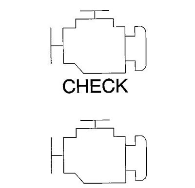
The indicator operating modes are listed below:
- The indicator lights up after the ignition is turned on before the engine starts. This is a test of the indicator lamp's functionality.
- If there are no fault codes in the ECM memory, the indicator goes out after the engine is started.
- If there are fault codes stored in the ECM memory, the indicator remains illuminated after the engine is started. The indicator goes out after three complete ignition cycles if the fault is no longer detected.
- The indicator starts to flash when misfires are detected, which can lead to damage to the catalytic converter.
Cylinder deactivation system
The cylinder deactivation system consists of:
- oil manifold;
- eight special valve lifters (two per cylinder to be switched off);
- gEN IV cylinder block;
- engine control unit.
To ensure maximum fuel economy at low engine loads, the control unit switches on the cylinder deactivation system for cylinders 1 and 7 on the left half bank and cylinders 4 and 6 on the right half bank, switching the engine to V4 operation. The engine operates in V8 mode when starting the engine, when idling and when operating at medium and high loads. The cylinders are deactivated by means of special tappets that prevent the opening of the intake and exhaust valves, see the description of the valve timing system in the chapter "Engine - mechanical part". The ECM limits the cylinder deactivation cycle to 10 minutes, then returns the engine to V8 operation for one minute. Switching between V8 and V4 modes occurs in approximately 250 milliseconds.
Reasons for prohibiting cylinder deactivation:
- low vacuum in the engine intake manifold;
- insufficient vacuum in the brake booster;
- pressing the accelerator pedal too hard;
- accelerator pedal position out of range;
- ignition voltage out of range;
- engine oil pressure out of range;
- engine oil temperature out of range;
- crankshaft speed out of range;
- incorrectly engaged automatic transmission gear;
- incorrect operating range of automatic transmission;
- the gear shifting process is in progress;
- all cylinders are activated by the diagnostic scanner;
- short-term operation according to the V8 scheme is not allowed;
- exceeding the maximum operating time according to the V4 scheme;
- aeration of engine oil occurs;
- fuel cut-off system activated;
- fuel cut-off timer activated;
- the temperature in the cabin is below the set value (heating and air conditioning systems);
- engine load limiting system active;
- active Brake Torque Control;
- the torque limiting system on the axle is active;
- engine overheat warning system active;
- catalytic converter overheat warning system is active;
- detonation combustion detection;
- engine speed limit warning system active;
- presence of fault codes:
- manifold Absolute Pressure Sensor;
- engine oil pressure sensor;
- coolant temperature sensor;
- vehicle speed sensor;
- crankshaft position sensor;
- misfires;
- cylinder deactivation system valve circuits;
Throttle control
The throttle actuator control performs the following functions:
- accelerator pedal position detection;
- setting the throttle position according to the driver's wishes and driving requirements;
- throttle position detection;
- conducting internal diagnostics;
- maintaining a set speed of movement ("cruise control");
- management of electrical energy consumption in the system.
The throttle control system includes:
- accelerator pedal position sensor;
- throttle body;
- engine control unit (ECM).
Accelerator pedal position sensor
The accelerator pedal assembly includes two individual pedal position sensors. The sensors are variable resistances connected to three electrical circuits:
- 5V reference voltage circuit;
- low voltage reference circuit;
- signal chain;
The first sensor, when the accelerator pedal is released, gives a signal below 1 V; when the pedal is pressed, the signal increases to 4 V. The second sensor has signals of 0.5 and 2 V, respectively.
Throttle body
The throttle body assembly includes:
- throttle valve;
- throttle actuator motor;
- two throttle position sensors.
The throttle valve is loaded with two springs, when the valve is closed there is a small gap between it and the body. When the valve is closed, the signal from the first sensor is 4 V, as the valve opens, the signal decreases to 1 V. The signal from the second sensor changes in the opposite direction.
Normal mode
When the throttle actuator control system is operating in normal mode, the following functions are used:
- minimum accelerator pedal position - when the engine control unit is turned on, the signal value corresponding to the minimum pedal position is updated;
- minimum throttle position - when the engine control unit is turned on, the throttle valve moves to the fully closed position and the signal value corresponding to this valve position is updated;
- "freezing of the throttle valve" - if the throttle valve is unable to reach a certain minimum position, the "freezing" mode of the valve is entered. In this mode, the control unit sends signals with the maximum pulse width to the drive motors several times in the direction of closing the valve;
- battery saving mode - after a certain time from the ignition being turned on without the engine being started, the control unit switches on the battery saving mode. In this mode, the voltage on the damper drive electric motor is minimal, and the damper is held in the closed position by springs.
Engine power reduction mode
When the control unit detects a malfunction in the throttle drive system, the engine power reduction mode is activated. This mode can be recognized by the presence of the following phenomena:
- acceleration limitation - the control unit continues to use the accelerator pedal to control the throttle, but the vehicle's acceleration is limited.
- throttle opening limitation - the control unit continues to use the accelerator pedal to control the throttle, but the throttle does not open fully;
- no response to the accelerator pedal - the control unit switches off the throttle actuator motor, the valve returns to the closed position under the action of the springs;
- "forced idle" - the control unit performs the following actions:
- limits engine speed either by throttle position or by fuel control or spark timing if the throttle valve is not moved.
- ignores signals from the accelerator pedal position sensors.
- the engine "stalls" - the control unit cuts off the fuel supply and the power supply to the throttle actuator.
Variable valve timing system
Variable valve timing system (camshaft position) - electrohydraulic, which is used to improve the engine's output parameters, in particular to reduce emissions of harmful substances, increase torque and reduce fuel consumption. When changing the position of the camshaft, the valve lift and the duration of the open position of the valves do not change. The entire range of change of the valve timing is 62 degrees of crankshaft rotation (31 degrees of camshaft rotation). For more information, see the lubrication system description in Chapter "Engine - mechanical part".
The camshaft position is controlled by a feedback circuit. To calculate the camshaft position, the engine control unit uses the following data:
- engine speed;
- the amount of vacuum in the intake manifold;
- throttle angle position;
- angular position of the camshaft;
- angular position of the crankshaft;
- relative position of the crankshaft and camshaft;
- coolant temperature;
- engine oil pressure;
- engine oil level;
- status of the variable valve timing solenoid circuit.
Fuel system
Fuel system on early models with fuel return line (the fuel pressure regulator is installed on the fuel manifold). On later models, the fuel system is returnless. Here, the fuel pressure regulator is installed in the fuel pump module, which eliminates the need for a return fuel line from the engine, which in turn allows for lower fuel tank temperatures. Lower fuel tank temperatures result in lower fuel vapor emissions.
Fuel tanks
The fuel tanks are made of high-strength plastic. Front(or the only one) the fuel tank is located on the left side of the vehicle. On dual tank models, the second fuel tank is located at the rear of the vehicle above the spare tire. The fuel tanks are secured with two metal straps.
The fuel tank filler neck has a built-in restrictor that prevents filling with leaded gasoline.
When filling into a dual fuel tank, fuel flows into both tanks simultaneously.
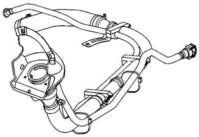
The filler neck is equipped with a tied cap equipped with a tightening torque limiter.
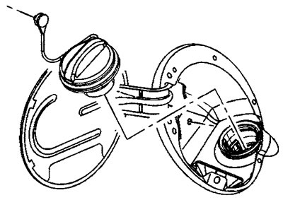
To install the cap, turn the cap clockwise until it clicks. This indicates that the cap is installed correctly and is properly tightened. Failure to install the cap correctly will result in the evaporative emission system not working properly.
Fuel pump module
The fuel pump module is installed in the fuel tank.
The fuel pump module contains:
- fuel level sensor;
- fuel pump;
- fuel filter;
- fuel tank pressure sensor (single tank or rear tank);
- fuel pressure regulator.
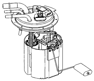
Front Fuel Pump Module (or the only one) fuel tank |
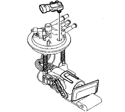
Rear Fuel Tank Fuel Pump Module |
Fuel supply system operating modes
Launch mode
After the ignition is turned on, the ECM energizes the fuel pump relay for two seconds to increase the pressure in the fuel system. During this time, the ECM calculates the air-fuel ratio for cranking based on signals from the coolant temperature, intake air flow/temperature, absolute air pressure and throttle position sensors. The system remains in the cranking mode until a certain engine speed is reached, as determined by the ECM.
Overflow purge mode
If the engine is "flooded" with fuel, purge the engine. To do this, press the accelerator pedal all the way down and crank the engine with the starter. Since the throttle valve is now wide open, the ECM reduces the pulse width of the fuel injectors to reduce fuel delivery. This condition is maintained as long as the throttle valve remains wide open and the engine speed is still below the set value. When the throttle valve is closed, the system returns to the starting mode.
Working mode
The operating mode has two control states: with and without feedback. When the engine is just started and the engine speed is above normal idle speed (warm-up), the system operates in an open-loop mode, i.e. the ECM ignores the signals from the oxygen sensors. The ECM now calculates the air-fuel ratio based on the signals from the coolant temperature, intake air flow/temperature, absolute air pressure and throttle position sensors. The system operates without feedback until the following condition occurs:
- both front oxygen sensors will not show a variable signal, which means both sensors are warm enough;
- the engine temperature has reached a certain value;
- after starting the engine, sufficient time has passed for warming up.
All the above values are different for each specific engine and are stored in the EEPROM memory. Once the above condition is reached, the system switches to the feedback control mode, maintaining the stoichiometric fuel-air ratio.
Acceleration mode
When the driver presses the accelerator pedal sharply, the air flow through the engine increases. To prevent possible lean mixture and subsequent "failure" in engine operation, the ECM (based on signals from different sensors) increases the width of the control pulse of the fuel injectors to slightly enrich the mixture, which is necessary for dynamic acceleration.
Slow-motion mode
When the driver releases the accelerator pedal, the air flow through the engine is reduced. The ECM reduces fuel supply until it is completely cut off if rapid deceleration or engine braking is required. Cutting off fuel supply prevents damage to the catalytic converters.
Battery voltage correction mode
When the battery voltage is low, the ECM provides low spark power compensation in the following ways:
- increase fuel supply;
- increase idle speed;
- increasing the idle time of energy accumulation in the secondary winding of the ignition coil.
Fuel cut-off mode
The ECM cuts off fuel supply in the following conditions:
- the ignition is turned off. This prevents the engine from running from glow ignition ("dieseling");
- the ignition is on but there is no ignition reference signal. This prevents fuel "flooding" or backfiring;
- engine speed is higher than permissible;
- the vehicle speed is too high, higher than the rated speed of the tires;
- when engine braking from high speed. This reduces hydrocarbon emissions and prevents backfires;
- during prolonged deceleration. This prevents damage to the catalytic converters.
Ignition system
The ignition system includes:
- Crankshaft Position Sensor Timing Ring - The crankshaft position sensor timing ring is part of the crankshaft. The ring has 58 teeth and a reference gap. The teeth of the ring are evenly spaced at 6-degree intervals. The two missing teeth create a 12-degree gap, which is used to create a timing reference pulse that identifies the TDC of the first cylinder. The timing pulse is used by the ECM to determine the ignition timing of a specific cylinder in the engine firing order.
- Crankshaft position sensor.
- Camshaft Position Sensor Synchronizing Ring - The camshaft position sensor synchronizing ring is part of the camshaft sprocket. The ring has two narrow teeth and 2 wide teeth located around the circumference of the ring. Front (or back) the edges of these 4 teeth are spaced at 90 degree intervals. The ECM uses signals from the narrow and wide teeth to determine the position of the camshaft, which cylinder is on the compression or expansion stroke, and the relative positions of the crankshaft and camshaft.
- Camshaft position sensor.
- Ignition coils - a total of eight ignition coils are used (one per cylinder).
- Engine Control Module (ECM) - The ECM controls all functions of the ignition system and continually adjusts the ignition timing. The ECM determines ignition timing based on input from sensors such as throttle position, coolant temperature, air flow/temperature, vehicle speed, gear position, and detonation.
Cruise control system
The cruise control system maintains the desired vehicle speed at speeds above 40 km/h.
The cruise control system includes:
- accelerator pedal;
- brake light switch (brake pedals);
- body electrical equipment control unit (BECU);
- cruise control switches;
- engine Control Unit (ECM);
- throttle actuator motor;
- vehicle speed sensor.
The cruise control system is activated and controlled by switches located on the steering wheel:
- switch ON/OFF
- switch +RES
- switch -SET
The switch signals are processed by the body control module (BCM). The BCM communicates the system switch status to the engine control module (ECM) via the GMLAN serial data circuit. The ECM uses the received data to determine and maintain the desired vehicle speed by controlling the throttle actuator.
To activate the system, turn the ON/OFF switch to the ON position and press the SET switch immediately. The engine control unit detects the current vehicle speed and sends a message via the GMLAN bus to the driver information display Cruise set to # # # (cruise control set to speed # # #). Pressing the accelerator pedal (with the cruise control system on) allows the driver to accelerate the car to a speed higher than the previously selected one. When the pedal is released, the system will return the car speed to the previously set value. The driver can change the speed maintenance task using the switches - SET or + RES. A single press of the switch - SET reduces the car speed by 1.6 km/h (but not lower than 37 km/h). Pressing the +RES switch once also increases the set vehicle speed by 1.6 km/h.
The speed maintenance system is deactivated when the brake pedal is depressed, when the system switch is turned to the OFF position, or when the CANCEL switch is pressed.
The engine control unit prohibits the operation of the cruise control system under the following conditions:
- If there is no communication between the engine control units and on-board electrical equipment.
- When cruise control system fault codes are detected.
- At speeds below 40 km/h.
- At too high speed.
- When the automatic transmission selector is in positions P, R or N or when driving in 1st gear.
- When the engine speed is too low or too high.
- When the voltage in the network goes beyond the range of 9-16 volts.
- When the anti-lock braking system is operating for more than two seconds.