


Caution: Before disconnecting fuel lines, clean the connectors and surrounding areas to prevent dirt from entering the system.
Note: The configuration of the parts varies depending on the model, please ignore the difference between the actual part and the part shown in the picture.
Series 1500
Capacity:
- long base 117 l
- short base 95 l
1. Relieve pressure in the fuel system.
2. Drain the fuel tank.
3. Disconnect the fuel tank ventilation hose connector (5) from the filler neck pipe.
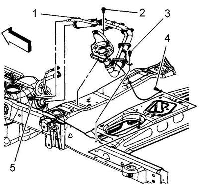
4. Disconnect the fuel vapor recovery system hose connector (4) from the tank.
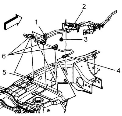
5. Disconnect the connector (5) of the fuel supply pipe between the tank and the chassis.
6. Plug all open holes.
7. Disconnect the fuel vapor recovery system hose (1) from the vapor canister.
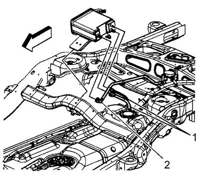
8. Plug open holes.
9. Place a jack under the tank.
10. Loosen the bolts of the fuel tank mounting straps.
11. Remove the fuel tank mounting straps.
12. With the help of an assistant, carefully lower the rear of the fuel tank.
13. Slide the front of the tank off the frame.
14. Lower the tank until you have access to the wire harness connectors.
15. Remove the wire harness connector holder (1).
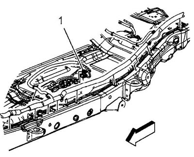
16. Disconnect the connector (1) of the fuel pump module and fuel pressure sensor.
17. Lower the fuel tank completely.
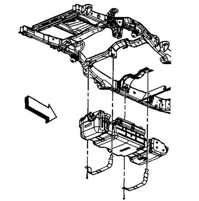
18. With the help of an assistant, move the tank to the workbench.
19. If the tank is to be replaced, perform the following operations, otherwise proceed to the installation procedure.
20. Remove the retainer (2) securing the fuel supply pipe to the tank.
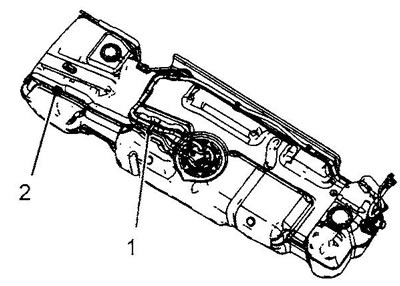
21. Open the clip (1) and remove the fuel supply pipe from it.
22. Disconnect the fuel supply line from the fuel pump module.
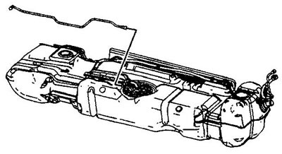
23. Remove the fuel supply pipe.
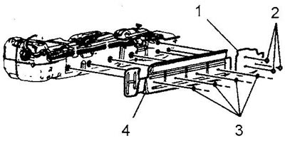
24. Remove the fasteners (2) and (3) of the screens (1) and (4) of the fuel tank, remove the screens.
25. Release the fuel vapor recovery system tubes from the clips (2) and (6).
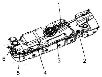
26. Open the clips (1), (3), (4) and (5), release the fuel vapor recovery system tubes.
27. Disconnect the fuel vapor recovery system tubes from the fuel pump module and the fuel tank vent valve.
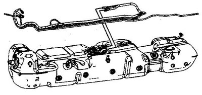
28. Remove the fuel vapor recovery system tubes from the tank.
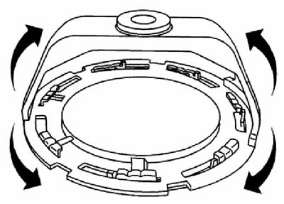
29. Using a special key, unscrew the fuel pump module mounting ring.
30. Carefully lift the pump module to gain access to the connector (1) under the module cover. Disconnect the connector.
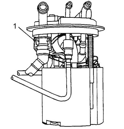
31. Remove the fuel pump module from the fuel tank.
32. Remove and discard the fuel pump module gasket.
Caution: Some fuel pump mounting rings have a stamped mark "DO NOT REUSE" (do not install again). However, such rings can be reinstalled if they are not damaged or deformed.
33. Place the fuel pump module mounting ring on a flat surface. Using a feeler gauge, measure the gap between the ring and the surface at 7 points.
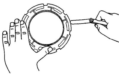
34. If the ring deformation is less than 0.41 mm, the ring does not require replacement. Otherwise, replace the ring.
35. Assembly and installation are carried out in reverse order.
36. After installation, check the system for leaks:
- a) Turn on the ignition for two seconds (do not start the engine).
- b) Turn off the ignition for ten seconds.
- c) Turn on the ignition (do not start the engine).
- d) Inspect the system, look for fuel leaks.
2500 Series Rear Tank
Capacity - 43.5 l
1. Relieve pressure in the fuel system.
2. Remove the spare wheel lock cylinder.
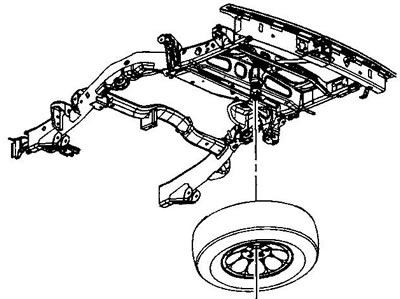
3. Remove the spare tire.
4. Drain the fuel tank.
5. Remove the rear exhaust heat shield.
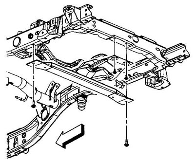
6. Loosen the bolts securing the spare wheel lift crossmember and remove the crossmember.
7. Disconnect the rear fuel tank evaporative emission system pipe from the fuel vapor canister.
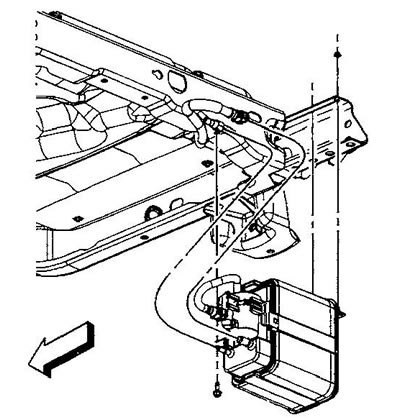
8. Disconnect the fuel vapor recovery system intermediate hose from the front tank.
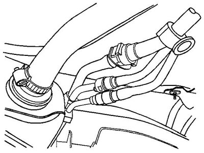
9. Disconnect the fuel pressure sensor connector (1).
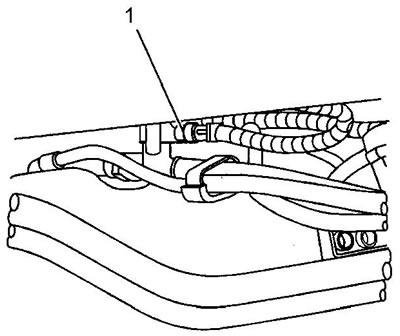
10. Place a jack under the fuel tank.
11. Loosen the bolts of the fuel tank mounting straps.
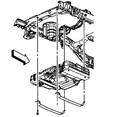
12. Remove the fuel tank straps.
13. With the help of an assistant, lower the rear tank so that the intermediate fuel line connectors are accessible.
14. Disconnect the fuel system pipes and the fuel vapor recovery system pipes from the rear tank.
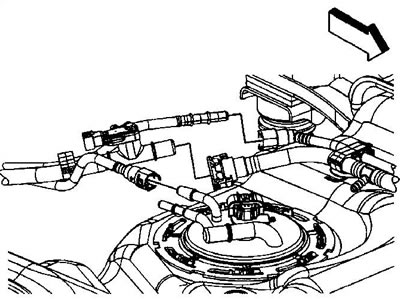
15. Remove the fuel system pipes and the fuel vapor recovery system pipes.
16. Plug open holes.
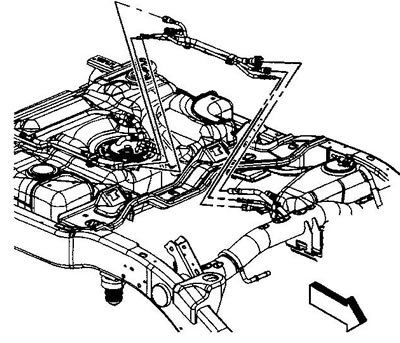
17. Disconnect the fuel pump module connector (2).
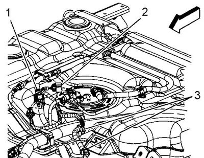
18. Lower the fuel tank completely.
19. Using an assistant, remove the tank from the jack.
20. When replacing the fuel tank, perform the following operations. Otherwise, proceed to the installation procedure.
21. Remove the fuel vapor recovery system tubes from the clip (1).
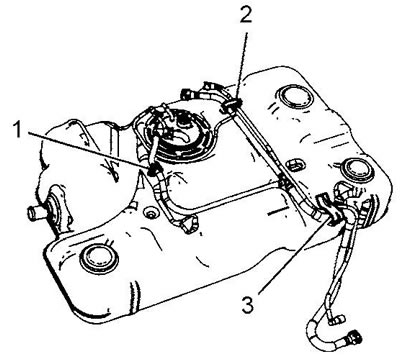
22. Open the clip (2) and remove the fuel vapor recovery system tubes from it.
23. Remove the fuel vapor recovery system tube from the clip (3).
24. Disconnect the fuel vapor recovery system tubes from the fuel pump module.
25. Remove the fuel vapor recovery system tube from the fuel tank.
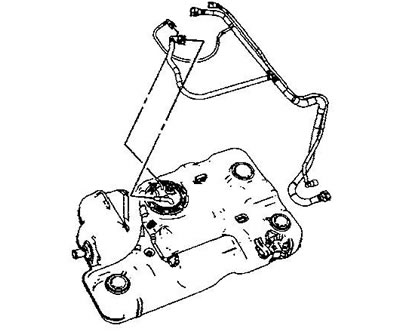
26. Using a special key, unscrew the fuel pump module mounting ring.
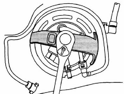
27. Carefully lift the fuel pump module to gain access to the pipe connector under the module cover.
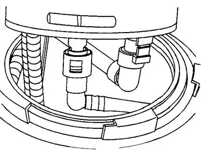
28. Remove the fuel pump module.
29. Remove and discard the fuel pump module gasket.
Caution: Some fuel pump mounting rings have a stamped mark "DO NOT REUSE" (do not install again). However, such rings can be reinstalled if they are not damaged or deformed.
30. Place the fuel pump module mounting ring on a flat surface. Using a feeler gauge, measure the gap between the ring and the surface at 7 points.
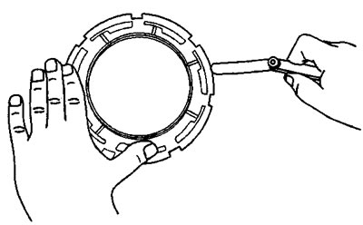
31. If the ring deformation is less than 0.41 mm, the ring does not require replacement. Otherwise, replace the ring.
32. Assembly and installation are carried out in reverse order.
33. After installation, check the system for leaks:
- a) Turn on the ignition for two seconds (do not start the engine).
- b) Turn off the ignition for 10 seconds.
- c) Turn on the ignition (do not start the engine).
- d) Inspect the system, look for fuel leaks.
2500 Series Front Tank
Capacity - 98.5 l
1. Relieve pressure in the fuel system.
2. Drain the fuel tank.
3. Disconnect the fuel vapor recovery system pipe connector (2) (filler neck) from the fuel tank ventilation valve.
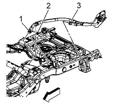
4. Disconnect the fuel vapor recovery system pipe connector (1) from the fuel tank vent valve.
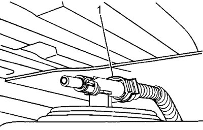
5. Disconnect the fuel system pipes and the fuel vapor recovery system pipes from the fuel tank.
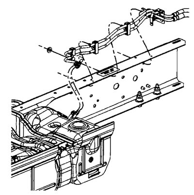
6. On the side of the fuel tank, open the intermediate fuel line support clip.
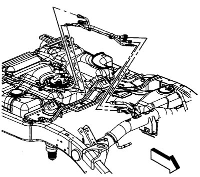
7. Disconnect the intermediate fuel supply and fuel vapor recovery system lines from the front tank lines.
8. Plug open holes.
9. Place a jack under the fuel tank.
10. Loosen the bolts of the fuel tank mounting straps.
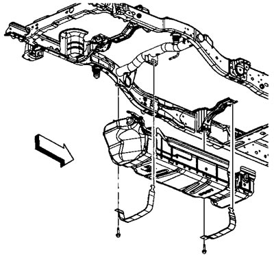
11. Remove the fuel tank mounting straps.
Caution: When lowering the fuel tank, make sure that the fuel lines do not touch anything.
12. With the help of an assistant, carefully lower the fuel tank until the wiring harness connectors are accessible.
13. Remove the wire harness connector retainer.
14. Disconnect the fuel pump module connector (1).
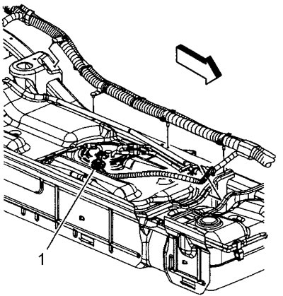
15. Lower the fuel tank completely.
16. Place the fuel tank on the workbench.
17. When replacing the fuel tank, perform the following operations. Otherwise, proceed to the installation procedure.
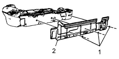
18. Remove the fasteners (1) of the fuel tank screen, remove the screen (2).
19. Release the fuel vapor recovery system tube from the clip (1).
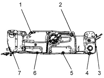
20. Open the clips (2-7) and release the fuel system and fuel vapor recovery system pipes.
21. Disconnect the fuel system and evaporative emission system pipes from the fuel pump module.
22. Remove the fuel system and fuel vapor recovery system pipes from the tank.
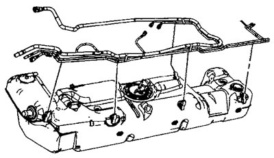
23. Using a special key, unscrew the fuel pump module mounting ring.
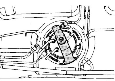
24. Carefully lift the pump module until you gain access to the tubing connector (1) under the module cover.
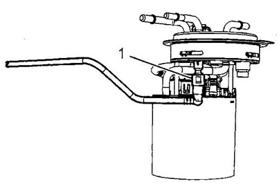
25. Remove the fuel pump module.
26. Remove and discard the fuel pump module gasket.
Caution: Some fuel pump mounting rings have a stamped mark "DO NOT REUSE" (do not install again). However, such rings can be reinstalled if they are not damaged or deformed.
27. Place the fuel pump module mounting ring on a flat surface. Using a feeler gauge, measure the gap between the ring and the surface at 7 points.
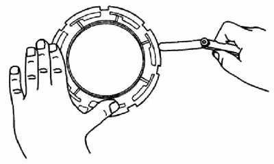
28. If the ring deformation is less than 0.41 mm, the ring does not require replacement. Otherwise, replace the ring.
29. Assembly and installation are carried out in reverse order.
30. After installation, check the system for leaks:
- a) Turn on the ignition for two seconds (do not start the engine).
- b) Turn off the ignition for ten seconds.
- c) Turn on the ignition (do not start the engine).
- d) Inspect the system, look for fuel leaks.
(The article was reprinted from the website: ChevyMan.ru)