


Contents: Disassembling the cup ↧ Disassembling the clutch ↧ Clutch assembly ↧ Adjusting the locking differential ↧ Differential assembly ↧
Disassembling the cup
8.6" and 9.5" gearboxes
1. Remove the driven gear of the gearbox.
2. Using a clamp, remove the regulator sleeve.
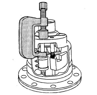
3. Remove the regulator assembly. To make it easier to remove the regulator, rotate the side gear so that the regulator fits between two teeth of the side gear.
4. Using a clamp, remove the latch bracket bushing. Remove the bracket. To make it easier to remove the bracket, rotate the side gear so that the bracket fits between two teeth of the side gear.
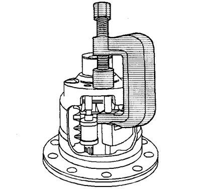
5. Remove the drive gear shaft fixing bolt.
6. Remove the drive gear shaft.
7. Remove the pinion gears and thrust washers through the differential cup windows. Mark the pinion gears and thrust washers for proper installation during reassembly.
8. Remove the thrust block.
9. Remove the right side gear and clutch disc assembly.
10. Remove the right side adjusting washer.
11. Remove the left side gear and clutch disc assembly.
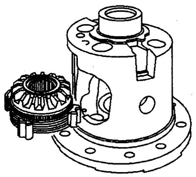
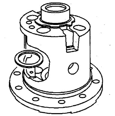
12. Remove the left side gear thrust washer.
Disassembling the clutch
8.6-inch gearbox - right side
1. Remove the guides (3).
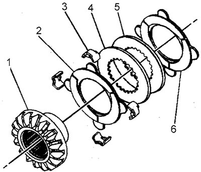
9,5 inch gearbox - right side
1. Remove the guides (2).
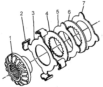
2. Remove the driven and leading clutch discs (2), (3), (4), (5), (6) and (7) from the side gear (1).
8.6" and 9.5" gearbox - left side
1. Measure and record the overall length of the left side gear assembly from the end of the gear to the thrust sleeve, including the side gear thrust washer.
2. Remove the clutch disc guides.
3. 9.5 inch gearbox: Using a bearing puller (2), mandrel (1) and press, remove the thrust sleeve from the gear.
8.6-inch gearbox: Remove the lock washer.
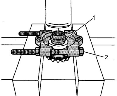
4. Disassemble the left side gear assembly:
- a) Remove the driven and leading clutch discs (7-14).
- b) Remove the spring washer (5).
- c) Remove the pressure plate (4).
- d) Remove the disc (3) with carbon coating.
- d) Remove the cam washer (2) from the side gear (1).
Caution: Do not replace the thrust bushing unless necessary.
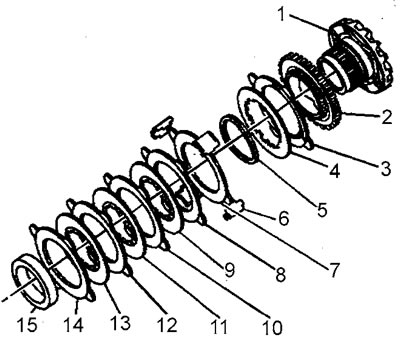
Disassembling the side gear assembly
Clutch assembly
8.6" and 9.5" gearbox - left side
1. Lubricate all discs with transmission oil.
2. Assemble the clutch in the order shown in the figure in the "Disassembly" section up to the moment of installing the retaining ring or thrust sleeve.
8.6 inch gearbox
3. Install the retaining ring (15).
4. Align the disc protrusions (3) with the cam washer grooves (2), press the clutch disc assembly together and install the retaining ring (15).
5. Install the guides (6). Apply grease to the guides to hold them in place.
9.5 inch gearbox
3. Align the projections of the disc (3) with the grooves of the cam washer (2). Install the thrust sleeve (15) on the side gear.
4. Using a mandrel and a press, press the thrust bearing onto the side gear.
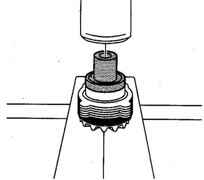
5. If the side gear or thrust sleeve has been replaced, measure the overall length of the gear:
- a) Install the clutch disc thrust washer onto the thrust sleeve.
- b) Measure the overall length of the assembly from the end of the gear to the thrust washer.
- c) Compare the obtained result with the value obtained during disassembly.
- d) If the new length differs from the old length by ±0.762 mm (0.003 in), select a new thrust washer with a thickness that is as close as possible to the old overall assembly length.
6. Align the ears of all driven clutch discs.
7. Install the guides (6). Apply grease to the guides to hold them in place.
8.6" and 9.5" gearbox - right side
Assembly is carried out in the reverse order of disassembly. To hold the guides in place, apply consistent grease to them.
Adjusting the locking differential
Note: If it was necessary to replace the left or right side gear assembly or the thrust block, the differential must be adjusted after replacement. The engagement clearances are adjusted by replacing the clutch disc adjusting washers and/or selecting the thrust block. Keep in mind that the correct selection of clearances is critical for the correct operation of the differential.
Left side gear clearance
1. Install the left side gear adjusting washer into the differential cup.
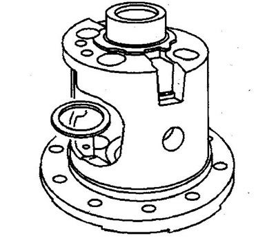
2. Install the left side gear assembly into the differential cup.
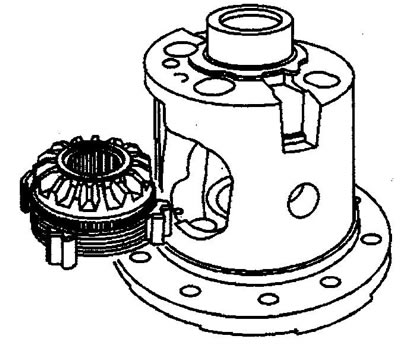
3. Install the drive gears and their thrust washers into the differential cup. Align the holes in the gears, thrust washers and cup for installing the gear axle.
4. Install the pinion shaft. It may be necessary to apply pressure to the left side pinion assembly to install the shaft. If the shaft cannot be installed even after the pinion assembly has been seated, install a thinner thrust washer under the pinion.
5. Install the axle fixing bolt, tighten the bolt by hand.
6. Turn the drive gear closest to the axle fixing bolt so that one tooth faces down, perpendicular to the flange of the driven gear of the gearbox.
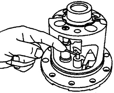
7. Install the copper pin between the side gear and the pinion shaft. Press the end of the pin until the clutch discs are compressed.
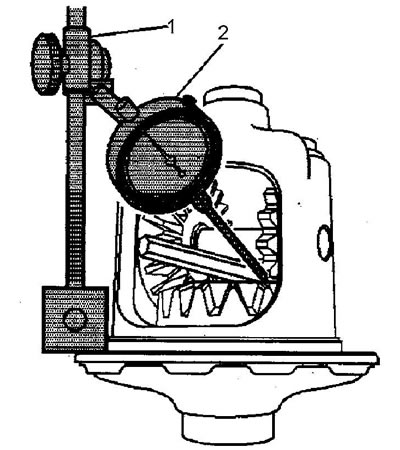
8. Measure the engagement clearance as follows:
- a) Install the magnetic stand (1) on the flange of the driven gear of the gearbox.
- b) Install the pointer indicator (2) on the stand.
- c) Place the indicator leg on one of the teeth of the differential drive gear, closest to the pinion axle fixing bolt. Set the indicator to zero.
- d) Press the drive gear against the differential cup.
- d) Rotate the drive gear from stop to stop and determine the amount of clearance in the engagement.
Gear clearance:
- 8.6 inch reducer - 0.25-0.40 mm
- 9.5 inch reducer - 0.28-0.42 mm
9. If the gap is too large, install a thicker clutch disc thrust washer; if it is too small, install a thinner washer. Washers are available in sizes from 0.6 to 1.32 mm with progressively increasing pitch.
Right side gear clearance
1. If necessary, remove the pinion shaft fixing bolt, pinion shaft, pinions with thrust washers, and left side gear assembly.
2. Install the right side gear adjusting washer into the differential cup.
3. Install the right side gear into the differential cup.
4. Install the differential drive gears with their thrust washers. Align the gear and thrust washers holes with the gear shaft mounting holes in the cup.
5. Using a copper pin, press the clutch disc pack of the right gear and install the drive gear shaft. If the shaft cannot be installed, install a thinner side gear adjusting washer.
6. Install the gear shaft fixing bolt, tighten the bolt by hand.
7. Turn the drive gear so that one tooth faces down, perpendicular to the flange of the driven gear of the gearbox.
8. Install the copper pin between the side gear and the pinion shaft. Press the end of the pin until the clutch discs are compressed.
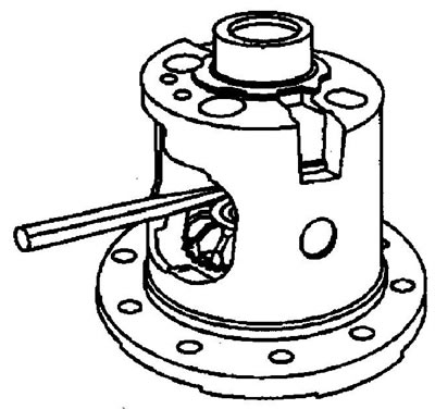
9. Measure the engagement clearance as follows:
- a) Install the magnetic stand (1) on the flange of the driven gear of the gearbox.
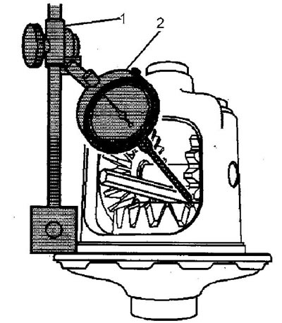
- b) Install the pointer indicator (2) on the stand.
- c) Place the indicator leg on one of the teeth of the differential drive gear, closest to the pinion axle fixing bolt. Set the indicator to zero.
- d) Press the drive gear against the differential cup.
- d) Rotate the drive gear from stop to stop and determine the amount of clearance in the engagement.
Gear clearance:
- 8.6 inch reducer - 0.076-0.23 mm
- 9.5 inch gearbox - 0.051-0.203 mm
10. If the gap is too large, install a thicker clutch disc thrust washer; if it is too small, install a thinner washer. Washers are available in sizes from 0.25 to 1.50 mm in 0.025 mm increments.
Adjusting the thrust block clearance
Caution: Before adjusting the thrust block clearance, the clearance in the engagement of the right and left side gears of the differential must be adjusted.
1. Install the left side gear clutch disc thrust washer.
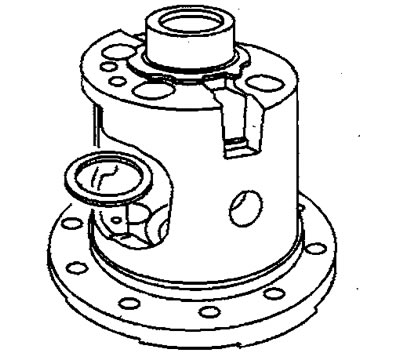
2. Install the left side gear assembly.
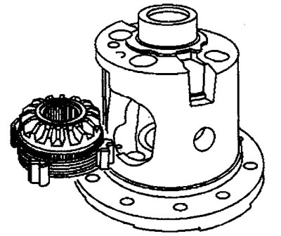
3. Install the right side gear thrust washer.
4. Install the right side gear assembly.
5. Install the drive gear shaft.
6. Install the gear shaft fixing bolt, tighten the bolt by hand.
7. Install a copper pin between the end of the left side gear and the axle of the drive gears. Press the free end of the pin until the clutch disc pack of the left gear is fully compressed.
8. Install a copper pin between the end of the right side gear and the axle of the drive gears. Press the free end of the pin until the clutch disc pack of the right gear is fully compressed.
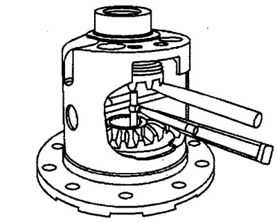
9. Using a telescopic gauge (25-50 mm), measure the distance between the ends (but not with teeth!) side gears.
10. Remove the telescopic gauge.
11. Measure the distance between the ends of the gauge. Record the result.
12. Compare the obtained result with the dimensions of the thrust blocks located. Select the block whose height is equal to the distance between the gears (see item 11).
13. If none of the blocks are the same size, choose the one with the next smaller height. For example, if the distance between the gears is 33.833 mm, choose the block with a height of 33.782 mm.
14. If the distance between gears is less than 33.578 mm (8.6 inch gearbox) or 40.488 mm (9.5 inch gearbox), install a clutch disc thrust washer of a smaller thickness on the left and/or right.
Note: After replacing the thrust or adjusting washer, check and, if necessary, adjust the clearance in the engagement.
15. If the distance between gears is more than 34.29 mm (8.6 inch gearbox) or 41.12 mm (9.5 inch gearbox), install a clutch disc thrust washer of greater thickness on the left and/or right.
Note: After replacing the thrust washer, check and, if necessary, adjust the clearance in the engagement.
16. Recheck and, if necessary, adjust the clearances in the engagement of the side gears.
17. Recheck the thrust block clearance and adjust if necessary.
18. Assemble the differential.
Differential assembly
Caution: Before assembling the differential, all clearances must be adjusted.
1. Install the left side gear clutch disc thrust washer.
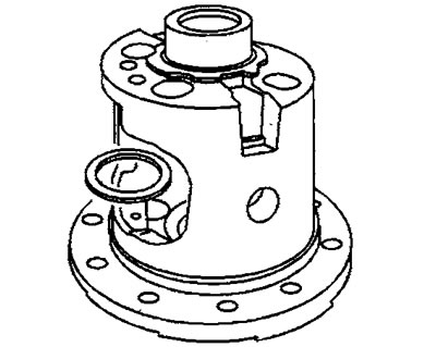
2. Install the left side gear assembly.
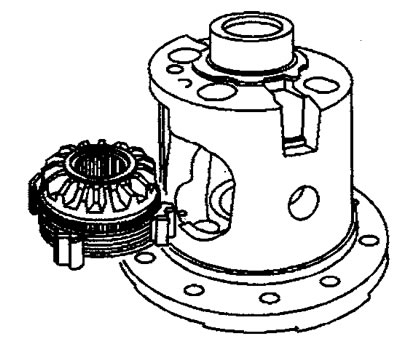
3. Install the right side gear thrust washer.
4. Install the right side gear assembly.
Note: If old gears and thrust washers are being installed, install them in the old locations.
5. Install the drive gears and their thrust washers.
6. Install the thrust block. The open side of the block should face the differential cup window.
7. Install the drive gear shaft.
8. Install the new pinion shaft fixing bolt. Hand tighten the bolt.
9. Install the regulator assembly.
10. Using a copper drift and a hammer, install the regulator locking sleeve so that the axial movement of the regulator is in the range of 0.25-1.27 mm.
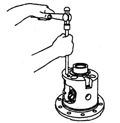
11. Install the locking bracket assembly. The straight end of the bracket spring should be above and off the governor shaft.
12. Using a copper drift and a hammer, install the bracket fixing sleeve so that the axial movement of the bracket is in the range of 0.00-0.051 mm.
13. Tighten the drive gear shaft fixing bolt. Tightening torque:
- 8.6 inch gearbox - 36 Nm.
- 9.5 inch gearbox - 50 Nm.
14. Install the driven gear of the gearbox.