


Contents: 8.6 inch gearbox ↧ 9.5 inch gearbox ↧
Attention:
- Adjustment of the differential side bearing preload must be completed before adjusting the gear clearance.
- To maintain the original clearance in the engagement when adjusting the preload in the bearings, install adjusting washers of the same thickness on the left and right.
- Measure the thickness of the adjusting washers and spacers individually. The total thickness of the adjusting package is determined by adding the individual measurements.
- Do not reinstall factory cast iron shims, use service shims and spacers instead.
8.6 inch gearbox
Wedge method
1. Install the drive gear of the gearbox.
2. Measure the torque of the pinion gear and record the result. Torque:
- new bearings 1.7-3.4 Nm.
- old bearings 1.1-2.3 Nm.
3. If the turning torque is out of tolerance, adjust it.
Caution: Before installing the gearbox, make sure that the differential side bearing seats are clean and free of burrs. Remember that tapered bearings are replaced only as a race-ring set.
4. Install the gearbox into the gearbox housing.
5. Install a 4.318 mm thick spacer on the left side of the crankcase.
6. Press the spacer against the crankcase by moving the gearbox to the left.
7. Install the clearance gauge on the right side of the crankcase between the adjusting washer and the outer race of the differential side bearing.
Caution: Excessive force when installing the device may deform the crankcase and lead to incorrect selection of the adjusting washer.
8. Tighten the button of the device until you get moderate resistance to moving the device.
9. Remove the device.
10. Remove the spacer.
11. Using a micrometer, measure the thickness of the spacer.
12. Using a micrometer, measure the thickness of the fixture at three locations around the circumference. Calculate the arithmetic mean of these three measurements. Record the measurement.
13. Add the values obtained in points 11 and 12. The sum will give the total thickness of the adjusting washers without preliminary load on the bearings.
14. Install a 1.016 mm thick adjusting washer between the outer race of the right side bearing and the gearbox housing.
15. Install the fixture to measure the gaps between the service spacer and the outer race of the left side bearing.
16. While rotating the driven gear in both directions, tighten the button of the device until the engagement clearance is approximately in the range of 0.0250.051 mm.
17. Remove the gap measuring device.
18. Remove the gearbox together with the side bearings and outer rings.
19. Remove the adjusting washer from the right side of the crankcase.
20. Using a micrometer, measure the thickness of the fixture in three places around the circumference. Calculate the arithmetic mean of these three measurements. This value will give the thickness of the adjusting shim on the left side of the gearbox.
21. To determine the right side shim thickness, subtract the left side shim thickness from the total shim stack thickness determined in step 13.
22. To obtain the required bearing preload and the required engagement clearance (approximately 0.1270.223 mm), add to the thickness of the adjusting washer on the right side (defined in paragraph 21) another 0.203 mm.
23. Assemble the adjustment package on the left side, consisting of a 4.318 mm thick spacer and an adjusting washer, the thickness of which is determined in paragraph 20.
24. Assemble the adjustment package on the right side, consisting of a 4.318 mm thick spacer and an adjusting washer, the thickness of which is determined in paragraph 22.
25. Install the gearbox with the differential side bearings and their outer rings.
26. Install the adjusting pack into the gearbox housing on the left side. The adjusting washer must be installed between the bearing ring and the spacer.
27. Install the spacer into the gearbox housing on the right side.
28. Install the adjusting washer, you may need to use a special puller. The adjusting washer should be installed between the bearing ring and the spacer.
29. Install the side bearing caps. Tighten the cap mounting bolts. Tightening torque 75 N·m.
30. Turn the drive gear of the gearbox several revolutions to fully seat the bearings.
31. Measure the gearbox turning torque. The total turning torque should be 0.57-1.13 N·m greater than the driving gear turning torque, which was determined earlier.
32. Calculate the preload of the side bearings as the difference between the values determined in items 2 and 31. Multiply the result obtained by the gear ratio of the gearbox (main gear). Preload 1.7-4.0 Nm.
33. If the preload of the side bearings is outside the permissible limits, change the thickness of the adjusting washers on the left and right by the same amount.
34. After setting the required bearing preload, check and, if necessary, adjust the clearance in the gearbox gear engagement.
35. After making all adjustments, check the position of the tooth contact patch.
Washer method
1. Install the drive gear of the gearbox.
2. Measure the torque of the pinion gear and record the result. Torque:
- new bearings 1.7-3.4 Nm.
- old bearings 1.1-2.3 Nm.
3. If the turning torque is out of tolerance, adjust it.
Caution: Before installing the gearbox, make sure that the differential side bearing seats are clean and free of burrs. Remember that tapered bearings are replaced only as a race-ring set.
4. Install the gearbox into the gearbox housing.
5. Install a 1.016 mm thick adjusting washer into the gearbox housing on the right side. Press the washer against the housing with the gearbox.
6. Install a 4.318 mm thick spacer into the crankcase on the left side.
7. Move the gearbox to the right until the clearance in the engagement between the driving and driven gears is completely eliminated.
8. While holding the gearbox in this position, install progressively thicker adjusting washers between the spacer and the outer race of the side bearing until the washer fits with moderate resistance.
9. After selecting the washer, measure its thickness in three places around the circumference, determine the arithmetic mean of the three measurements. Write down the result.
10. Install this washer between the spacer and the outer race of the differential side bearing.
11. Remove the 1.016 mm thick washer from the right side of the crankcase.
12. Install a 4.318 mm thick spacer into the crankcase on the right side.
13. Move the gearbox to the left and repeat operations according to points 7 and 8.
14. After selecting the washer, measure its thickness in three places around the circumference, determine the arithmetic mean of the three measurements. Write down the result.
15. To preload the side bearings and set the initial engagement clearance at 0.13 mm, do the following:
- a) Subtract 0.752 mm from the measurement result in point 9.
- b) Add 0.356 mm to the measurement results in item 14.
16. Select adjusting washers of the required thickness for the right and left sides of the gearbox. Check the thickness of the washers in three places around the circumference.
17. Install the left side adjusting washer between the spacer and the outer ring of the side bearing.
18. Move the gearbox to the left.
19. Install the right-hand adjusting washer between the spacer and the outer race of the side bearing. You may need to use a special puller.
20. Install the side bearing caps. Tighten the mounting bolts. Tightening torque 75 N·m.
21. Turn the drive gear of the gearbox several revolutions to fully seat the bearings.
22. Measure the gearbox turning torque. The total turning torque should be 0.57-1.13 N·m greater than the driving gear turning torque, which was determined earlier.
23. Calculate the preload of the side bearings as the difference between the values determined in items 2 and 23. Multiply the result obtained by the gear ratio of the gearbox (main gear). Preload 1.7-4.0 Nm.
24. If the preload of the side bearings is outside the permissible limits, change the thickness of the adjusting washers on the left and right by the same amount.
25. After setting the required bearing preload, check and, if necessary, adjust the clearance in the gearbox gear engagement.
26. After making all adjustments, check the position of the tooth contact patch.
9.5 inch gearbox
Caution: Before installing the gearbox, make sure that the differential side bearing seats are clean and free of burrs. Remember that tapered bearings are replaced only as a race-ring set.
1. Remove the gearbox.
2. Measure the torque of the pinion gear and record the result. Torque:
- new bearings 1.7-3.4 Nm.
- old bearings 1.1-2.3 Nm.
3. If the cranking torque is less than the minimum permissible value, tighten the drive gear nut in small portions.
4. If the cranking torque is greater than the maximum permissible value, replace the deformable spacer of the drive gear.
5. Install the gearbox.
6. Take measures to prevent the gearbox from falling out of the crankcase.
7. Move the gearbox to the right until the clearance in the gearbox gear engagement is taken up. Do not use force to take up the clearance. If ZERO clearance cannot be obtained, rotate the bearing adjustment nut until the clearance is taken up.
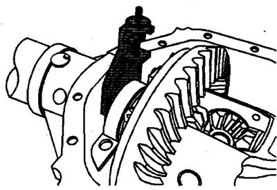
8. While holding the gearbox in this position, rotate the bearing adjustment nut until the nut contacts the side bearing ring.
9. After the nut and bearing ring have made contact, tighten the nut an additional two notches.
10. Install the retainer and adjusting nut retainer bolt.
11. Unscrew the bolts securing the left side differential bearing cover.
12. Remove the left side bearing cover.
13. Install the clearance measuring device into the gearbox housing on the left side between the housing and the outer bearing ring.
14. Tighten the button of the device until you get moderate resistance to moving the device.
15. Remove the device.
16. Measure the thickness of the fixture in three places around the circumference.
17. Calculate the arithmetic mean value - this will give the thickness of the adjusting washer.
18. Select the required adjusting washer.
19. Install the washer between the crankcase and the outer race of the differential bearing.
20. Install the left side differential bearing cover.
21. Install the left bearing cover mounting bolts. Tighten the mounting bolts by hand.
22. Loosen the bearing adjusting nut retainer bolt.
23. Remove the bearing adjustment nut retainer.
24. Turn the nut to securely press the adjusting washer against the gearbox housing.
25. Rotate the drive gear of the gearbox to seat the bearings.
26. Turn the right bearing adjustment nut until the nut moves away from the bearing ring.
27. Turn the bearing adjustment nut in the opposite direction until the nut with the bearing ring is engaged.
28. After the nut and ring of the right bearing have made contact, tighten the nut by three notches for new bearings or by two notches for old bearings.
29. Install the nut retainer.
30. Install the retainer mounting bolt and tighten the bolt by hand.
31. Tighten the bearing cover mounting bolts. Tightening torque 85 N·m.
32. Tighten the bearing adjustment nut retainer bolt. Tightening torque 26 N·m.
33. Rotate the drive gear of the gearbox to seat the bearings. Measure the total turning torque of the gearbox. Turning torque:
- new bearings 3.9-6.2 Nm.
- old bearings 2.8-5.1 Nm.
34. Calculate the actual bearing tension as the difference between measurements in items 2 and 33. Multiply the resulting value by the gear ratio of the gearbox (main gear). The preload of the side bearings should be 1.7-4.0 Nm.
35. If the bearing preload is outside the permissible limits, change the thickness of the adjusting washer.
Note: Adjusting washers are available in thicknesses from 5.6 to 6.55 mm with a step of 0.05 mm.
36. After adjusting the tension, check and, if necessary, adjust the clearance in the gear engagement of the gearbox.
[The article was borrowed from the website «ChevyMan»]