
Gearbox gears can be manufactured using two different manufacturing methods (with two or five undercuts). Gears with two undercuts are marked with a circular groove along the ends of the teeth of the driven gear and a circular groove along the shaft body of the driving gear. The configuration of the tooth contact patch for both types of gears is slightly different: with an inclination from the top to the root of the tooth (two undercuts) and without this tilt (five undercuts). Regardless of the gear type, the contact patch should be located symmetrically relative to the tooth centerline. The contact patch position is affected by the engagement gap and the position of the drive gear of the gearbox.
Verification procedure
1. Wash the differential cup and the toothed rims of both gears of the reduction gear. There should be no traces of oil on these parts.
2. Tighten the differential side bearing cap bolts to the specified torque.
3. Apply the parking brake so that the gearbox rotates when a torque of 14 Nm is applied.
Warning: Performing the test without a load on the gearbox will not give the correct result.
4. To apply marking paint sparingly, use a medium-hard brush. Apply paint to all teeth of the driven gear.
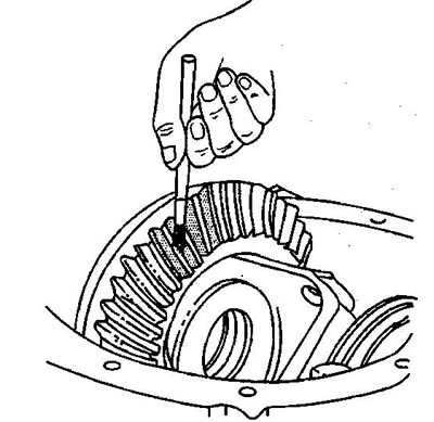
5. Turn the drive gear so that the driven gear makes three full revolutions.
6. Turn the drive gear in the opposite direction so that the driven gear makes three full revolutions.
7. Compare the configuration of the contact patch with the examples shown in the figures.
Correct configuration
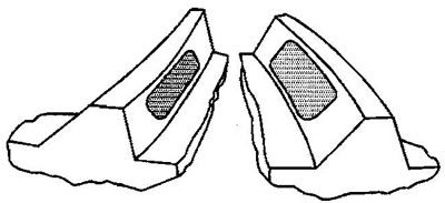
Condition: The position of the pinion gear and the engagement clearance are correct.
Correction: Not required.
Service Recommendations: Looseness of the pinion bearings or differential cup may cause a change in the shape of the contact patch from tooth to tooth, which is still in the normal position. If this is the case, check the preload value of all bearings. If the preload is correct, there may be damage to the components and/or improper assembly.
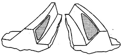
Outward displacement on the working side of the tooth - inward displacement on the non-working side of the tooth
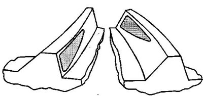
Condition: Incorrect clearance in the engagement. The driven gear is moved away from the driving gear.
Correction: Reduce the engagement gap. Move the driven gear toward the leading gear by replacing the differential side bearing adjusting washer.
Inward displacement on the working side of the tooth - outward displacement on the non-working side of the tooth
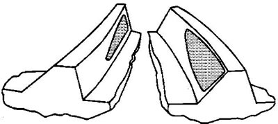
Condition: Incorrect clearance in the engagement. The driven gear is pushed towards the driving gear.
Correction: Increase the engagement clearance. Move the driven gear away from the driving gear by replacing the differential side bearing adjusting washer.
Outward displacement on the working side of the tooth - Outward displacement on the non-working side of the tooth
Condition: Incorrect clearance in the engagement. The driven gear is moved away from the driving gear.
Correction: Reduce the engagement gap. Move the driven gear toward the leading gear by replacing the differential side bearing adjusting washer.
Inward displacement on the working side of the tooth - inward displacement on the non-working side of the tooth
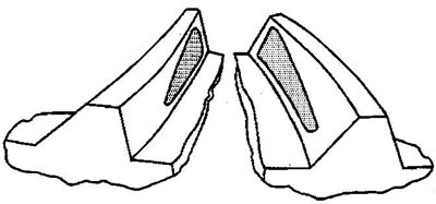
Condition: Incorrect clearance in the engagement. The driven gear is pushed towards the driving gear.
Correction: Increase the engagement clearance. Move the driven gear away from the driving gear by replacing the differential side bearing adjusting washer.
Displacement towards the apex of the tooth
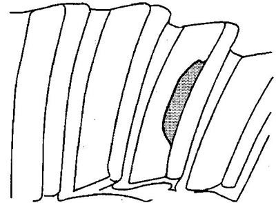
Condition: The drive gear is offset from the driven gear.
Correction: Move the drive gear closer to the driven gear by increasing the thickness of the drive gear adjusting shim.
Displacement towards the tooth root
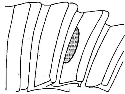
Condition: The drive gear is pushed towards the driven gear.
Correction: Move the drive gear away from the driven gear by reducing the thickness of the drive gear adjusting shim.