
Contents: Removal ↧ Installation ↧
Note: This procedure requires a proprietary GM camshaft locking device#J-44221 or equivalent.
Removal
1. Set the engine to a position where the first piston is at TDC (see chapter 2B). Remove the valve cover (see subsection 4) and front engine cover (see subsection 6).
2. Move the chain tensioner away and secure it by inserting a drill into the hole.
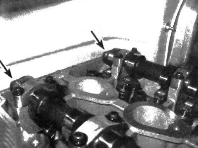
3. Remove the upper chain guide (see illustration).
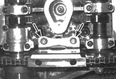
7.3. Unscrew the two indicated bolts and remove the upper chain guide
4. Remove the exhaust camshaft drive unit (see illustration). When the bolt tightening force is loosened, it is necessary to fix the camshaft by grasping it with an open-end wrench by the hex section (see illustration).
7.4a. The exhaust camshaft drive device is secured with the designated hexagonal socket bolt in the head
7.4b. When loosening the sprocket bolt tightening force, it is necessary to secure the camshaft by grasping it with an open-end wrench by the designated hexagonal section
5. Remove the intake camshaft sprocket (see illustration), then disconnect it from the crankshaft sprocket and remove the chain. When the tension on the sprocket bolt is released, it is necessary to secure the camshaft by grasping it with an open-end wrench by the hex section, as in the operation described in the previous paragraph.
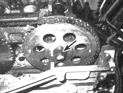
7.5. Intake camshaft sprocket bolt
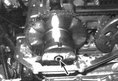
6. Remove the two service port plugs located at the front of the cylinder head (see illustration).
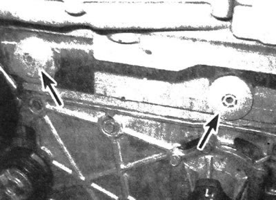
7.6 Using a hex key, unscrew the designated plugs of the service holes located in front of the cylinder head bolt
7. Remove the drive chain tensioner shoe bolt (right) and the chain guide bolt (left), then remove the shoe and guide. Remove the tensioner (if it is supposed to be replaced).
8. Remove the crankshaft sprocket.
Installation
Note: to align the initial position of the chain, every seventh link has a darker color.
9. If necessary, install the tensioner and tighten it to the required torque.
10. Install the shoe and guide and tighten their bolts to the required torques.
11. Install the two service port plugs and tighten them to the specified torque.
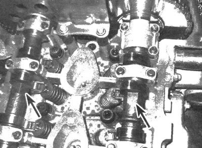
12. Make sure the number one piston is still at TDC, then install the camshaft locking tool. The cams located at the front of the shafts should be facing upwards, and the grooves located on the rear tails of the camshafts should also be facing upwards (see illustration).
7.12. When the first piston is at TDC (on the compression stroke) the grooves located on the rear tailpieces must be facing upwards and parallel to the upper plane of the cylinder head (the grooves are used to connect the locking device)
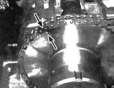
13. Install the crankshaft sprocket, then place the chain on the intake camshaft sprocket so that the dark link in the chain aligns with the mark on the sprocket.
14. Pass the chain through the cylinder head and place it on the crankshaft sprocket, aligning the mark on the sprocket with the dark link.
15. Install the sprocket onto the intake camshaft.
Note: To align the sprocket with the camshaft pin, you may have to remove the locking tool and rotate the shaft slightly.
Install the locking device.
16. Raise the drive chain and guide the exhaust camshaft drive unit to its original location, making sure that the mark on the drive unit sprocket is aligned with the dark link in the chain.
17. Install the actuator onto the intake camshaft without tightening the bolt completely.
Note: To align the sprocket with the camshaft pin, you may have to remove the locking tool and rotate the shaft slightly.
18. Turn the exhaust camshaft actuator clockwise (when viewed by an observer located in front of the device) all the way.
Caution: The drive unit must be installed in the full advance position (turned fully clockwise), otherwise, engine damage may occur.
Tighten the bolt to the specified torque.
19. Tighten the intake camshaft sprocket bolt to the specified torque.
20. Remove the drill bit from the tensioner, then remove the camshaft locking tool.
21. Using the marks, make sure that the valve timing mechanism phases are aligned (see illustrations).
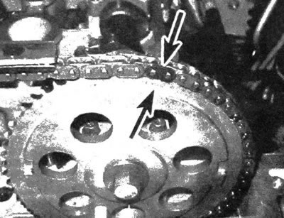
7.21a. When the chain is installed correctly (when the first piston is at TDC on the compression stroke) the mark on the intake camshaft sprocket should align with the dark link...
7.21b....and also the mark on the exhaust camshaft drive unit (the mark on the sprocket should also align with the dark link)
22. The rest of the assembly is carried out in the reverse order of removal.