


Contents: Drive coupling assembly ↧ Pulley and bearing assembly ↧ Clutch coil ↧ Checking the operation of the clutch ↧ Compressor oil balancing ↧ Compressor oil balancing procedure ↧
Drive coupling assembly
Necessary equipment
Retaining device for clamping sleeve
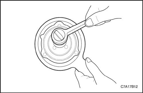
Disassembly procedure
1. Remove the compressor. See "Compressor" in this section.
2. Use Clutch Hub Holding Tool J-33027 to hold the driven plate and clutch hub assembly from turning.
3. Unscrew the shaft nut using a shaft nut socket.
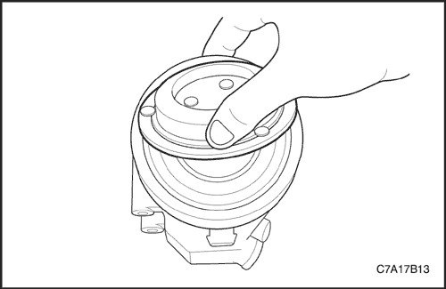
4. Pull out with your hands and remove the drive coupling assembly.
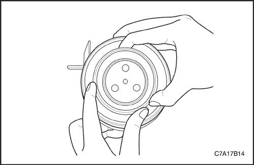
Assembly order
1. Install the drive coupling assembly.
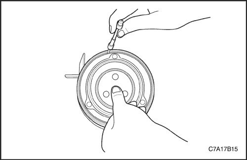
2. Roughly check the air gap with a wire gauge by pressing the drive coupling assembly before fastening the shaft bolt. (Air gap 0.3~0.6mm)
Note: If the air gap is not within specifications, replace the adjusting shim with another shim that creates the correct gap.
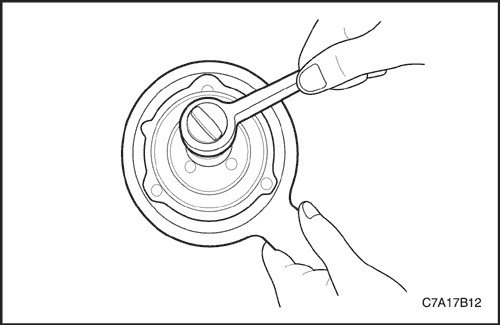
3. Tighten the fastening nut of the driven disk and the clutch hub assembly.
Tighten
Tighten the drive coupling assembly mounting nut to 13 N·m (10 ft·lbs).
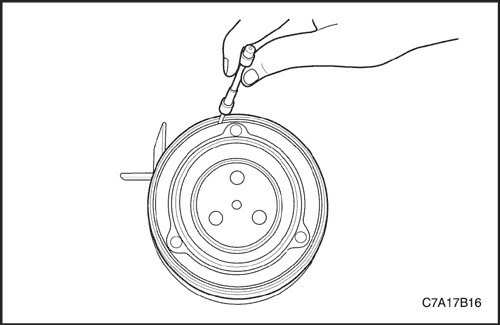
4. Recheck the air gap with a feeler gauge. (Air gap 0.3~0.6mm)
5. Install the compressor. See "Compressor" in this section.
Pulley and bearing assembly
Disassembly procedure
1. Disconnect the negative battery cable.
2. Evacuate the refrigerant. See "Procedures for discharging, refilling oil, vacuuming and charging the air conditioning system" in this section.
3. Remove the compressor. See "Compressor" in this section.
4. Remove the drive coupling assembly. See "Drive coupling assembly" in this section.
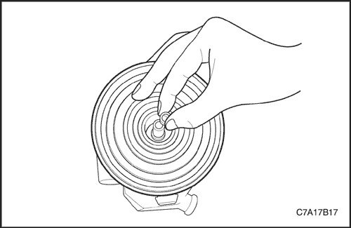
5. Remove the adjusting shims from the end of the shaft.
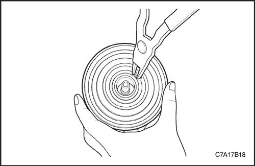
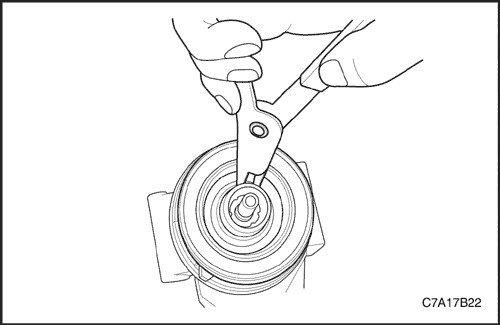
6. Remove the pulley and bearing assembly retaining ring.
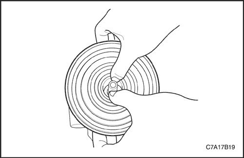
7. Pull the pulley upward with both hands until the pulley and bearing assembly are released.
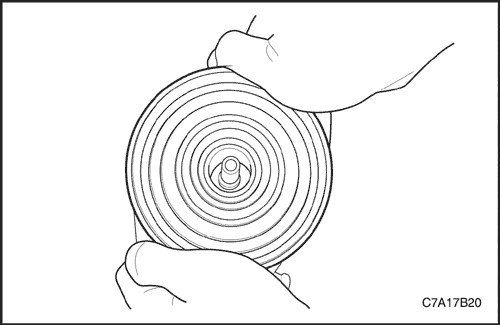
Installation procedure
Note: Do not use a hammer to avoid damaging the pulley bearing.
1. Position the rotor pulley evenly and precisely on the front cover housing.
2. Increase the pressure on the pulley surface with both hands.
Important: Listen for a distinct change in sound during the installation process to ensure proper seating.
3. Rotate the pulley quickly by hand to ensure that the pulley is installed correctly.
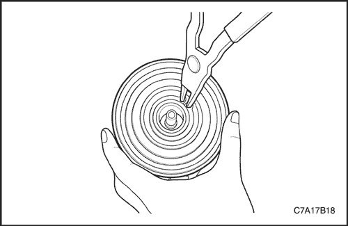
4. Install the pulley and bearing retaining ring assembly.
5. The sharp edge of the spool stopper should be located at the top.
6. To ensure proper assembly, crimping is required after installation.
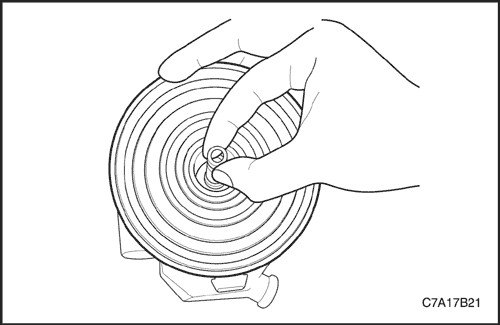
7. Determine the number and type of adjusting shims to obtain an air gap in the range of 0.3~0.6 mm.
8. Install adjusting shims on the end of the shaft.
9. Install the drive coupling assembly. See "Drive coupling assembly" in this section.
10. Install the compressor. See "Compressor" in this section.
Clutch coil
Removal procedure
1. Disconnect the negative battery cable.
2. Evacuate the refrigerant. See "Procedures for discharging, refilling oil, vacuuming and charging the air conditioning system" in this section.
3. Remove the compressor. See "Compressor" in this section.
4. Remove the drive coupling assembly. See "Drive coupling assembly" in this section.
5. Remove the pulley and bearing assembly. See "Pulley and bearing assembly" in this section.
6. Remove the coil retaining ring.
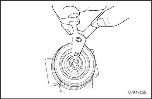
7. Remove the coil and housing assembly.
Installation procedure
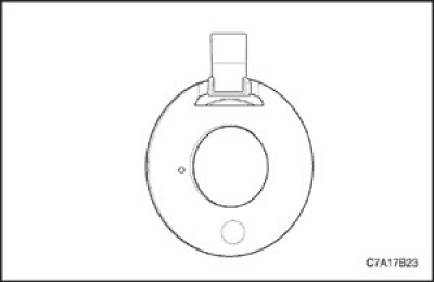
1. Before assembly, make sure that the protrusion on the coil plate is located in the installation groove of the compressor pump so that the coil cannot rotate.
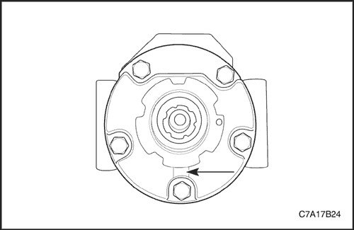
2. The mounting hole on the coil plate must be positioned on the compressor pump mounting pin to prevent the coil from rotating. (Only VM Diesel)
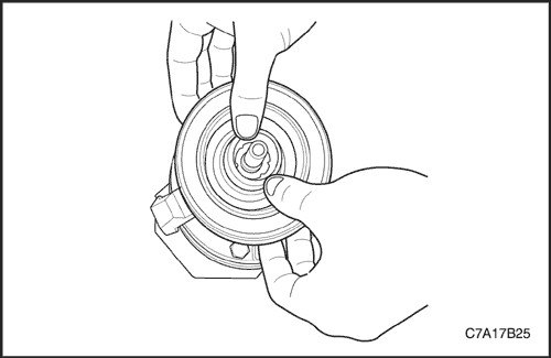
3. Install the coil and housing assembly.
Note: The spool retaining ring will not seat if the spool is not installed correctly.
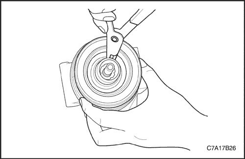
4. The beveled edge of the spool stopper should be positioned at the top.
5. Install the coil stopper and housing assembly.
Note: To ensure proper assembly of the stopper, crimping is required after installation.
6. Install the pulley and bearing assembly. See "Pulley and bearing assembly" in this section.
7. Install the drive coupling assembly. See "Drive coupling assembly" in this section.
8. Install the compressor. See "Compressor" in this section.
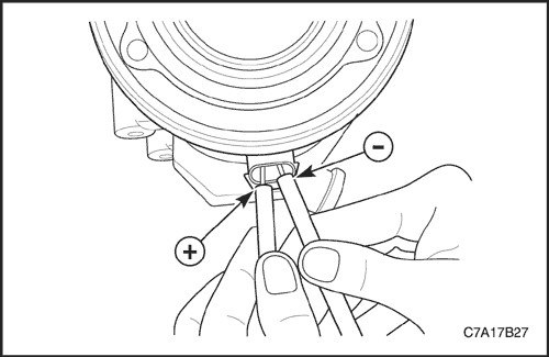
Checking the operation of the clutch
1. Engage and disengage the clutch more than 2 times to ensure that the clutch functions normally.
2. If the clutch does not engage within 1 second under 10.5 V, check the coil resistance. (Nominal coil resistance is 3.3 ohms±4% at 25°C)
Caution! When checking the clutch operation, there should be no polarity change in the coil connector. If this happens, the diode will short-circuit.
Compressor oil balancing
All SP17 compressors are supplied with 150 +/- 10 cc of oil.
Care must be taken to ensure that the correct amount of oil is supplied to the air conditioning system when charging it. Insufficient oil will cause compressor durability problems. Excess oil in the system may cause knocking noises when the compressor starts.
Compressor oil balancing procedure
Compressor oil can be charged and drained through the suction/discharge ports.
When the compressor is removed from the vehicle for service, there are two ways to properly balance the A/C oil:
1. First method: Completely flush the air conditioning system with running water and use a brand new SP17 compressor, already charged with 150 cc of oil.
2. Second way:
- Drain the lubricating oil from the compressor and measure its volume. Measure the amount removed. (Normally, the SP17 compressor should hold 15~60 cc of oil)
Note: If there is a major loss of oil, such as cracks in the compressor housing, damage to the condenser, flush the air conditioning system with running water and install a new compressor for replacement. Lubrication check is not required.
- Remove all lubricating oil, approximately 150 cm³, from the new replacement compressor.
- Fill the new replacement compressor with lubricating oil in the same quantity as measured in operation a). Use the "new" oil removed from the replacement compressor.
(The original source of the article is the website ChevyMan.ru)