ChevyMan.ru
Mazda Mitsubishi Toyota Land Rover Honda Kia Nissan
English Русский
Български
Беларускі
Український
Српски
Hrvatski
Română
Polski
Slovenský
Magyar
|
Articles | Sitemap | Contacts |


Home   Aveo   Captiva   Cruze   Lacetti   Lanos   Niva   Tahoe   Others  
Tahoe 2 and 3 (2000-2014) Tahoe 1 (1992-2000)
  • Home
  • Tahoe
  • 1 (1992-2000)
  • Transmission
  • Clutch and drive shafts
  • Replacing axle shaft covers and checking CV joints

Replacing axle shaft covers and checking CV joints (Chevrolet Tahoe 1)

            0

Contents: Inner CV joint ↧ Outer CV joint ↧
1. Remove the axle shaft. If the axle shaft is equipped with a boot casing, cut off the clamps and remove the casing.

2. Place the axle shaft in a vice.

Inner CV joint


3. Cut the clamps and move the boot to the center of the axle shaft. Mark the position of the hinge housing (tee) and remove the housing from the hinge crosspiece.

4. Remove the crosspiece of the joint by removing the retaining rings (to access the rings, move the hinge in both directions) (see photo).
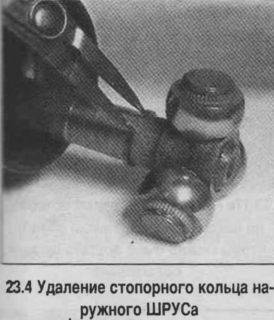
4. Remove the crosspiece of the joint by removing the retaining rings (to access the rings, move…


5. Wrap the cross bearing with tape.

5. Wrap the cross bearing with tape.
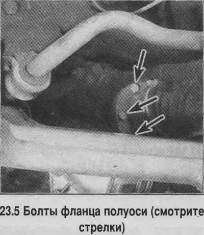

6. Remove the crosspiece from the axle shaft.

7. Remove the cover.

8. Clean the housings and the crosspiece. Remove and wash the crosspiece bearings. Inspect the rollers, crosspiece, and bearings.


9. Place half of the grease supplied with the new cover into the CV joint housing, and place the rest of the grease into the cover.

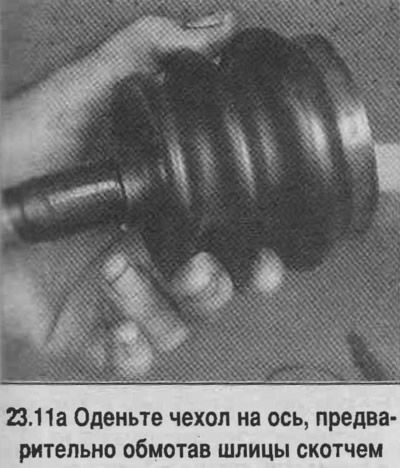
10. Put the cover on the axle, having first wrapped the splines with tape (see photo).

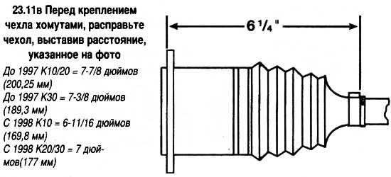
11. Assemble the joint, keeping the distance shown in the photo. Install the housing according to the marks made during disassembly. Insert the retaining rings into the grooves on the axle shaft. Straighten the boot and tighten the clamps.
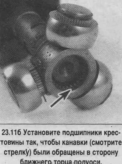
11. Assemble the joint, keeping the distance shown in the photo. Install the housing according to…


11. Assemble the joint, keeping the distance shown in the photo. Install the housing according to…


11. Assemble the joint, keeping the distance shown in the photo. Install the housing according to…


Outer CV joint


12. Remove the cover mounting ring by tapping it with a hammer and punch and moving it, avoiding deformation (see photo).
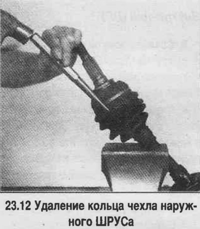
12. Remove the cover mounting ring by tapping it with a hammer and punch and moving it, avoiding…


13. Cut off the cover clamps.

14. Remove the retaining ring and outer joint (see photo).
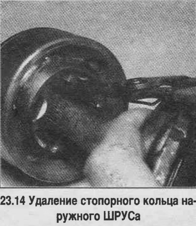
14. Remove the retaining ring and outer joint (see photo).


15. Remove the old cover.

16. Mark the orientation of the collar and the hinge holder.

17. Disassemble the hinge according to the photo.
17. Disassemble the hinge according to the photo.
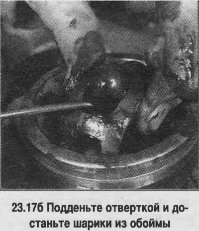

17. Disassemble the hinge according to the photo.
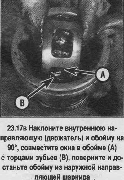

17. Disassemble the hinge according to the photo.
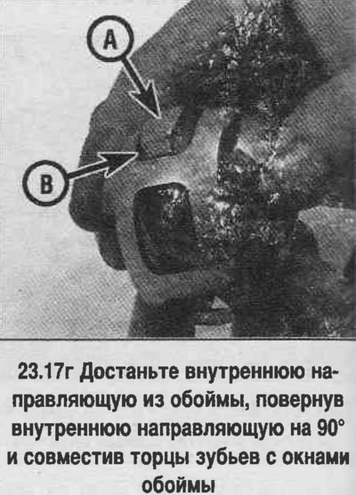

17. Disassemble the hinge according to the photo.


18. Clean the parts and check their condition. Polished areas may appear, which are traces of normal operation of the joint (see photo).
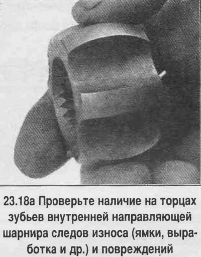
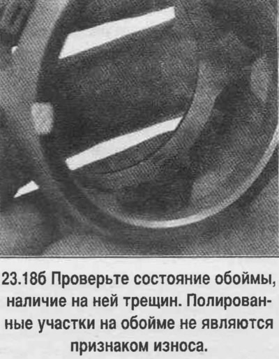

18. Clean the parts and check their condition. Polished areas may appear, which are traces of…


18. Clean the parts and check their condition. Polished areas may appear, which are traces of…


19. Install the inner guide into the cage in the reverse order of removal.

20. Install the inner guide with the collar into the outer guide in the reverse order of removal. The marks that were previously applied to the inner guide and collar after assembly should be visible.

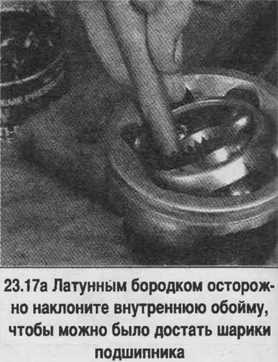
21. Install the balls into the cage (see photo).
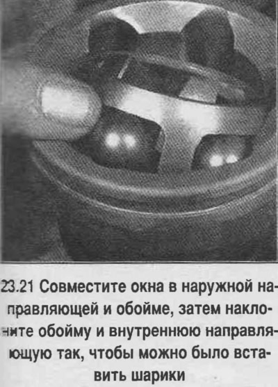
21. Install the balls into the cage (see photo).


22. Load the joint with grease through the inner spline hole. Distribute the grease so that it enters the bearing by inserting a wooden mandrel into the spline hole and acting as a piston. Repeat the procedure until the bearing is completely lubricated (see photo).
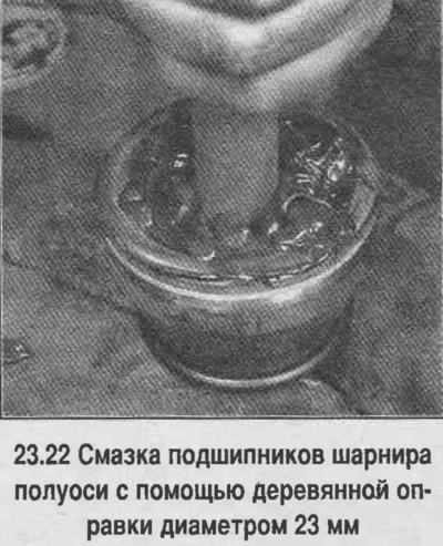


22. Load the joint with grease through the inner spline hole. Distribute the grease so that it…


23. Install the boot on the axle shaft. Apply grease into the boot cavity.

24. Install the assembled CV joint on the axle shaft, aligning the splines. Press the CV joint onto the retaining ring, which should fit into the groove of the joint.

25. Secure the cover with clamps, first tucking the edges of the cover into the grooves.

26. Then assembly is carried out in reverse order.

Information taken from the official website CHEVYMAN

The article was checked: Vladimir Romannikov
This article is available at russian, bulgarian, belarusian, ukrainian, serbian, croatian, romanian, polish, slovak, hungarian

Share information:

Previous articles
Tahoe 1: Clutch and drive shafts
Next articles

Front axle shaft (4WD models) — removal and installation
Brake Hub/Drum and Wheel Bearings — Removal, Installation and Adjustment
Rear axle — removal and installation
Main gear shaft seal — replacement
Fully unloaded axle shaft — removal and installation
Front axle shaft with housing (all-wheel drive models) — removal and installation


See similar articles on the topic of Chevrolet cars:
Replacing the wheel drive shaft seal Chevrolet Aveo T250 (2006-2011)
Replacing the intermediate shaft seal of the front drive axle Chevrolet Captiva 1 (2006-2018)
Checking and replacing engine management system sensors Chevrolet Cruze 1 (2008-2016)
Checking the condition and replacing the timing belt Chevrolet Lacetti 1 (2002-2009)
Checking the condition and replacing the air conditioning compressor drive belt Chevrolet Lanos T150 (2002-2009)
Checking the rear axle beam Chevrolet Niva 1 (2002-2016)
Checking the condition of the axle shaft boots (every 3000 miles or 3 months) Chevrolet Lumina 1 (1989-1994)
Link in different formats to this page


Visitor comments

No comments yet


How much will 15 + 44 =


Tahoe 2 and 3 (2000-2014) 
  • General information
  • Vehicle characteristics
  • Vehicle device
  • Manual
  • Maintenance
  • Power unit
  • Engine repair
  • Engine overhaul
  • Cooling system
  • Injection and control system
  • Exhaust system
  • Engine electrical equipment
  • Transmission
  • Automatic gearbox 4L60, 4L65, 4L70
  • Automatic gearbox 6L50, 6L80, 6L90
  • Transfer case
  • Drive shafts and cardan
  • Front drive axle
  • Rear drive axle
  • Chassis
  • Car suspension
  • Steering
  • Brake system
  • Body (until 2007)
  • Exterior (external elements)
  • Interior (internal elements)
  • Doors, locks and windows
  • Heating and air conditioning
  • Security System (SRS)
  • Body (since 2007)
  • Exterior (external elements)
  • Doors, locks and windows
  • Interior (internal elements)
  • Electrical equipment
  • Electrical appliances (until 2007)
  • Lighting and lamps (until 2007)
  • Audio system (until 2007)
  • Electrical appliances (since 2007)
  • Lighting and lamps (since 2007)
  • Audio system (since 2007)
  • Wiring diagrams (2000-2005)
  • Wiring diagrams (2005-2007)
  • Wiring diagrams (since 2007)


Tahoe 1 (1992-2000) 
  • General information
  • User manual
  • Maintenance
  • Power unit
  • Engine in a car
  • Engine removed
  • Cooling system
  • Heating and air conditioning
  • Fuel and exhaust systems
  • Decreased toxicity
  • Transmission
  • Manual gearbox
  • Automatic gearbox
  • Transfer case
  • Clutch and drive shafts
  • Chassis
  • Brake system
  • Car suspension
  • Steering
  • Body
  • Repair of body elements
  • Electrical equipment
  • Engine electrics
  • Equipment and devices
  • Electrical circuits


ChevyMan.ru © 2017-2026 · Mobile version · Feedback · Site search · Interesting to read · Sitemap: EN BG BY UA RS HR RO PL SK HU

Aveo 2003-2008 · Aveo 2006-2011 · Aveo 2012-2018 · Captiva 2006-2018 · Cruze 2008-2016 · Lacetti 2002-2009 · Lanos 2002-2009 · Niva 2002-2016 · Tahoe 1992-2000 · Tahoe 2000-2014 · Lumina 1 1989-1994 · Trailblazer 1 2001-2008 · Orlando 1 2010-2018 ·
🛡️ For your security and to improve our service, this site uses cookies. You can disable them in your browser.