
Contents: Removal ↧ Installation ↧
Removal
Warning:
- The battery contains compressed gas. Always use special tools and follow the instructions given here, otherwise there is a risk of injury.
- Do not heat the battery.
- Do not attempt to repair the battery.
- Before disposing of a used battery, drill a hole of approximately 1.5 mm in diameter at the end of the battery opposite the location where the sealing ring is installed.
- Removal the pushrod is not recommended. Incorrect installation of the pushrod into the brake booster piston may result in loss of brakes. If the pushrod requires service, replace the booster assembly.
1. Apply the parking brake and block the wheels.
2. Press the brake pedal at least 10 times to release the pressure in the accumulator.
3. Remove the brake master cylinder.
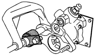
4. Install the support mandrel on the booster stud and on the end of the battery.
5. Screw the nut onto the stud.
6. Clamp the battery. If the battery does not move with moderate force, remove the clamp and press the brake pedal 10 more times.
7. Turn the locking ring (2) until either end of the ring fits under the inspection hole (1).
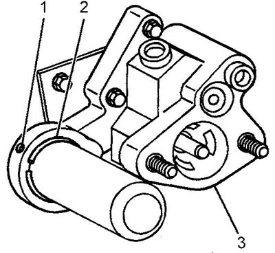
8. Press and hold the locking ring (2) with a small pin inserted into the inspection hole (1).
9. Using a hook, remove the battery retaining ring (1).
10. Remove the clamp.
11. Unscrew the support mandrel fastening nut.
Removing the retaining ring (1) of the hydraulic brake booster accumulator
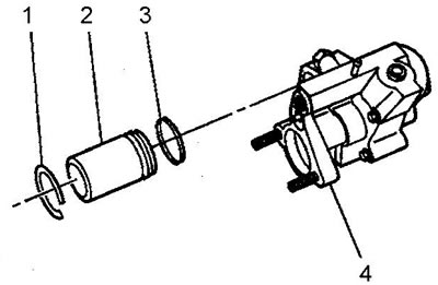
12. Remove the mandrel.
13. Remove the battery (2) and sealing ring (3).
Installation
14. Installation is carried out in the reverse order. Before installation, lubricate the seals with power steering fluid.