
Contents: Electrical connector ↧ Checking harnesses and electrical… ↧ Road test ↧ Checking functionality ↧ Engine stop test ↧ Switching delay test ↧ Hydraulic test ↧ Manual Shift Test ↧ Checking the unit's condition ↧ Drive disk runout ↧ Bending and blockage of radiator… ↧ Primary shaft speed sensor and… ↧ Gearbox range switch ↧ Gearbox fluid temperature sensor ↧ Solenoid switching valve (No. 1,… ↧ Solenoid pressure regulator valve ↧ Repairs performed on the vehicle… ↧
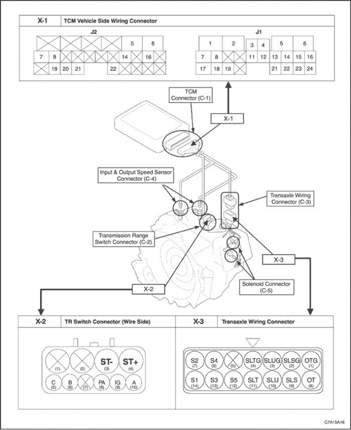
Electrical connector
|
X-1: Side harness electrical connector
|
|||||||
|
Electrical connector J1
|
Electrical connector J2
|
||||||
|
1
|
Grounding
|
5
|
Secondary shaft speed sensor (-)
|
||||
|
2
|
Solenoid valve for regulating pipeline pressure
|
6
|
Input shaft speed sensor (-)
|
||||
|
3
|
Torque Converter Clutch Lock-Up Pressure Regulator Solenoid Valve (-)
|
7
|
Signal "B" (Automatic transmission range switch)
|
||||
|
4
|
Solenoid valve for regulating pressure in hydraulic drive lines (+)
|
8
|
Signal "A" (Automatic transmission range switch)
|
||||
|
5
|
Torque Converter Clutch Lock-Up Pressure Regulator Solenoid Valve (+)
|
14
|
Secondary shaft speed sensor (+)
|
||||
|
6
|
Battery
|
16
|
Input shaft speed sensor (+)
|
||||
|
7
|
High Speed CAN (-)
|
19
|
Signal "PA" (Automatic transmission range switch)
|
||||
|
8
|
High Speed CAN (-)
|
20
|
Signal "C" (Automatic transmission range switch)
|
||||
|
11
|
Gearbox fluid temperature sensor (+)
|
21
|
Ignition
|
||||
|
12
|
Gearbox fluid temperature sensor (-)
|
22
|
Voltage
|
||||
|
13
|
SS4 Shift Solenoid Valve
|
-
|
-
|
||||
|
14
|
SS3 Shift Solenoid Valve
|
-
|
-
|
||||
|
15
|
SS2 Shift Solenoid Valve
|
-
|
-
|
||||
|
16
|
SS1 Shift Solenoid Valve
|
-
|
-
|
||||
|
17
|
High Speed CAN (+)
|
-
|
-
|
||||
|
18
|
High Speed CAN (+)
|
-
|
-
|
||||
|
19
|
Shift Pressure Regulating Solenoid Valve (-)
|
-
|
-
|
||||
|
21
|
Shift Pressure Regulating Solenoid Valve (+)
|
-
|
-
|
||||
|
22
|
SS5 Shift Solenoid Valve
|
-
|
-
|
||||
|
23
|
Grounding
|
-
|
-
|
||||
|
24
|
Serial data for starting auxiliary equipment by signal
|
-
|
-
|
||||
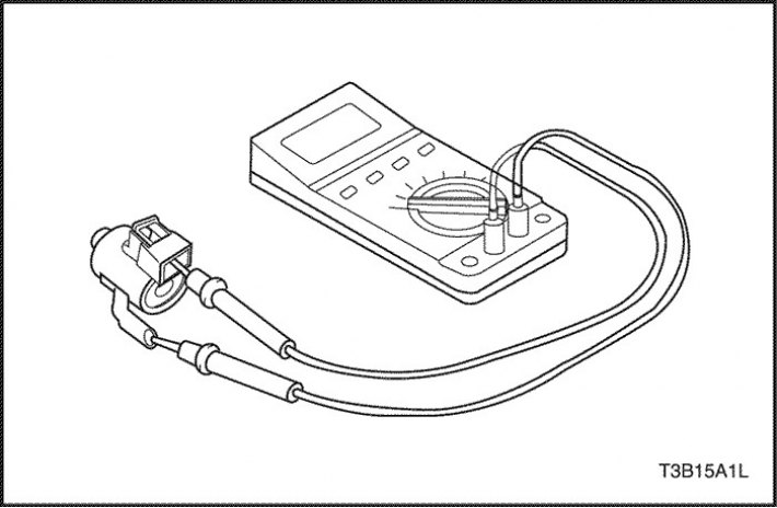
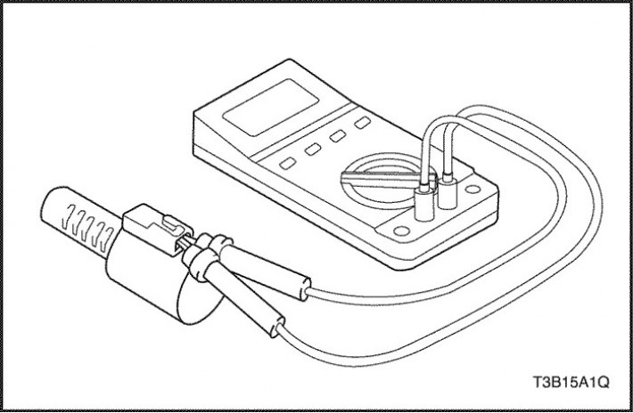
Checking harnesses and electrical connectors
1. Test with reproduction of fault conditions
Conduct a test reproducing the conditions for the occurrence of the malfunction symptoms based on the vehicle owner's description. Refer to the conditions listed below.
- Road conditions at the time of the malfunction, speed, acceleration, braking, straight-line driving, turning, air temperature, weather conditions, etc.
2. Check the connection of the electrical connector blocks.
Check the connectors visually and for tightness of connection.
- Dismemberment of the connector
- Corrosion of contacts
- Deformation of contacts or looseness of the joint
3. Check the wiring harness for internal breakage.
Disconnect the connectors from both ends of the harness and check the resistance between the corresponding contacts of the pads.
- Normal condition: 1 ohm or less (there is no break)
- Fault condition:? Ohm (chain break)
Note: Measure the resistance by gently shaking the harness in vertical and horizontal directions.
A break in the circuit in the middle of the harness is very rare. In most cases, the contact failure occurs in the connector block.
4. Check the harness for a short circuit.
Disconnect the connectors from both ends of the harness and check the resistance between the corresponding contacts of the connector and the body ground.
- Normal condition: 1 Mohm or higher (there is no short circuit)
- Fault condition: low resistance (short circuit)
Measure the resistance between two contacts of one connector (except for power and ground contacts).
- Normal condition: 1 Mohm or higher (there is no short circuit)
- Fault condition: low resistance (short circuit)
Note: Measure the resistance by gently shaking the harness in vertical and horizontal directions.
The cause of a short circuit is often a malfunction in the places where the harness is attached to the body.
5. Intermittent contact in the connector.
If no other cause for the fault code can be determined, the most common cause is an intermittent electrical connector contact.
The connector pads should be inspected and cleaned and the stored fault code should be cleared.
Road test
Road tests of a vehicle are carried out to diagnose signs of a malfunction and to check the correctness of the repair.
Before performing a road test, ensure that the oil is warm (50°C (122°F) ~ 80°C (176°F)).
1. D-range test
- Check the serviceability of upshifting, downshifting, downshifting and gear shift locking.
- Perform engine braking.
- Check for unusual jerking, noise, or shifting roughness.
2. Test in the "P" range
Brake the vehicle on a slope (more than 5°), move the gearshift lever to position "P" and release the parking brake mechanism.
Make sure that the parking lock pawl does not allow the vehicle to roll.
Checking functionality
Before carrying out the inspection, the following conditions must be met.
- The oil is heated (50°C (122°F) ~ 80°C (176°F)).
- The switches for the air conditioner, lighting, etc. are in the Off position.
Engine stop test
The purpose of the engine stall test is to check the overall performance of the automatic transmission and engine by determining the speeds in the "D" and "R" ranges at which the engine stalls.
1. Chock all four wheels and apply the parking brake. Make sure the vehicle is stationary.
2. Press the brake pedal with your left foot.
3. Shift into ranges "D" and "R" and fully depress the gas pedal with your right foot.
Check the speed at which the engine stalls.
|
Norm
|
2.4L
|
2640 rpm
|
|
3.2L/2.0S Diesel
|
2,489 rpm
|
Note: Do not test for more than 5 seconds at a time, as this will cause the oil to overheat.
An interval of at least 1 minute should be maintained between tests.
|
Engine Stop Test Results
|
Cause of malfunction
|
|
Below normal
in both "D" and "R" ranges
|
Insufficient engine power
Torque converter overrunning clutch malfunction
|
|
Above normal
only "D"
|
Low pressure in hydraulic lines
Malfunction (slippage) forward clutches (C1)
Overrunning Clutch Malfunction #2 (F2)
|
|
Above normal
only "R"
|
Low pressure in hydraulic lines
Malfunction (slippage) direct drive clutches (C2)
Malfunction (slippage) 1st gear and reverse brakes (B3)
|
|
Above normal
in both "D" and "R" ranges
|
Low pressure in hydraulic lines
Brake Malfunction B5
Oil filter failure (clogged)
Oil leakage in the circuits of each range
|
Switching delay test
This type of test determines the time until a slight jolt is felt when the gearshift lever is moved from position "N" to "D" and from "N" to "R" with the engine idling.
The shift delay test allows you to determine the condition of hydraulic systems and friction clutches/brakes.
1. Chock all four wheels and apply the parking brake. Make sure the vehicle is stationary.
2. Determine the delay time by measuring with a stopwatch the time from the moment the gearshift lever is moved from position "N" to "D" and from "N" to "R" until a slight jolt occurs.
|
"N" → "D"
|
less than 0.7 s
|
|
"N" → "R"
|
less than 1.2 sec
|
Note: It is necessary to take measurements three times and then determine the average value.
An interval of at least 1 minute should be maintained between tests. (To relieve residual pressure from clutches/brakes.)
|
Switching delay test results
|
Cause of malfunction
|
|
Longer than normal for "N" → "D"
|
Low pressure in hydraulic lines
Malfunction (slippage) forward clutches (C1)
Overrunning Clutch Malfunction No.2 (F2)
|
|
Longer than normal for "N" → "K"
|
Low pressure in hydraulic lines
Malfunction (slippage) direct drive clutches (C2)
Malfunction (slippage) 1st gear and reverse brakes (B3)
Brake Malfunction B5 (slippage)
|
Hydraulic test
Necessary equipment
J-21867-50 Hydraulic Line Pressure Adapter
J-21867 Pressure Gauge
The hydraulic test is performed to determine the operating conditions inside the automatic transmission by measuring the line pressure for the "D"/"R" ranges "idle"/"when the engine is stopped".
1. Chock all four wheels and apply the parking brake. Make sure the vehicle is stationary.
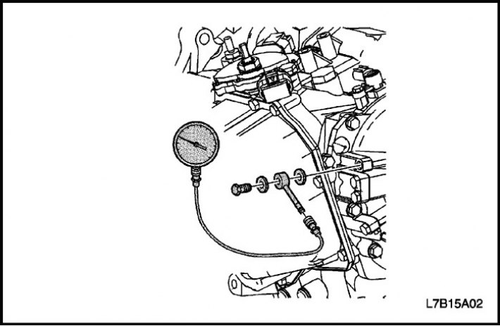
2. Install J-21867 and J-21867-50 into the hydraulic line leak test hole.
3. With your left foot, fully depress the brake pedal, switch to the "D" and "R" ranges and measure the pressure "at idle"/"when the engine is stopped".
|
Pressure in hydraulic drive lines, MPa (pounds per square inch)
|
D
|
R
|
|
At idle
|
0.33-0.39 (47.86-56.56)
|
0.50-0.62 (72.52-89.92)
|
|
When the engine stops
|
1.28-1.40 (185.65-203.05)
|
1.71-1.99 (248.01-288.63)
|
Note: Do not test for more than 5 seconds at a time, as this will cause the oil to overheat.
An interval of at least 1 minute should be maintained between tests.
Make sure there are no oil leaks after installing the pressure gauge adapter.
|
Hydraulic test results
|
Cause of malfunction
|
|
Above normal
in both "D" and "R" ranges
|
Malfunction of the electromagnetic valve for regulating pressure in the hydraulic drive lines
Primary regulator valve failure
|
|
Below normal
in both "D" and "R" ranges
|
Malfunction of the electromagnetic valve for regulating pressure in the hydraulic drive lines
Primary regulator valve failure
Oil pump malfunction
Brake Malfunction B5
|
|
Below normal
only "D"
|
Low pressure in hydraulic lines
Brake Malfunction B5 (slippage)
Hydraulic circuit "D" fault
Forward clutch fault (C1)
|
|
Below normal
only "R"
|
Hydraulic circuit "R" malfunction
Direct Drive Clutch (C2) Malfunction
1st gear and reverse brake malfunction (B3)
Brake Malfunction B5
|
Manual Shift Test
This type of test is carried out to determine the nature of the fault: electrical or mechanical.
1. Disconnect the electrical connector of the shift solenoid valve. Make sure that the ranges and gears in the manual shift mode are as shown in the table below.
|
Range
|
Broadcast
|
|
D
|
4th gear
|
|
R
|
Back
|
Note: Only the shift solenoid harness should be disconnected.
Checking the unit's condition
Drive disk runout
- Check the disc runout for compliance with the norm.
|
Norm
|
within 0.2 mm (0.008 inches)
|
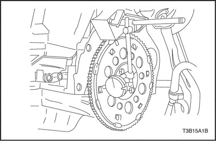
Action:
If the runout is not within the norm, replace the disc.
If excessive wear or blockage of the torque converter bushing or oil pump is detected, the torque converter and automatic transmission should be replaced.
Note:
- When assembling the torque converter and drive disk, use bolts of the required type and length. When the bolt rests against the front cover of the torque converter, the friction lining of the locking clutch is damaged. This results in a "complete locking" type malfunction.
- Do not tighten bolts with an impact wrench.
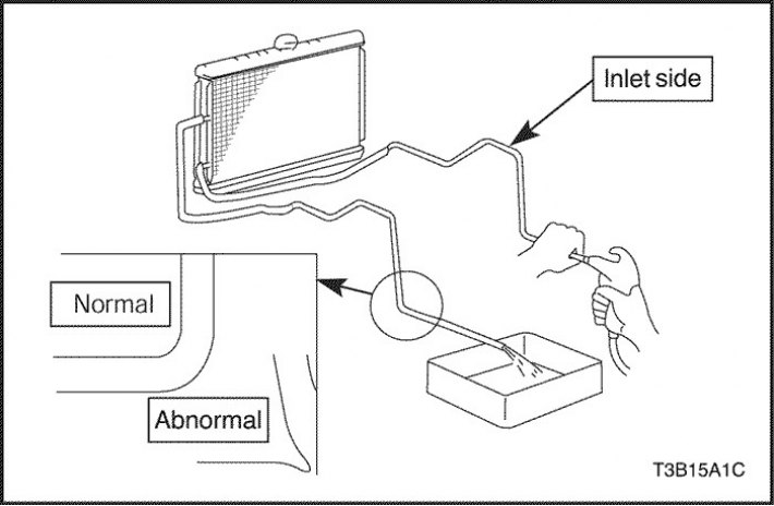
Bending and blockage of radiator tubes
- Check the radiator tubes for excessive bending, deformation or small flow area.
Action: Replace faulty parts.
- Apply air under pressure of 2 kg/cm? to the radiator inlet pipe. Make sure the pipe is passable by observing the air coming out of the other end.
Action: Clean the pipeline.
Primary shaft speed sensor and secondary shaft speed sensor
1. Remove the primary or secondary shaft speed sensor connector, connect 12 V power supply, a 100 Ohm resistance and an ohmmeter to the contact. (Observe polarity)
2. Check the high and low signal current by shaking the magnet from side to side near the tip of the speed sensor. (The gap is within 5 mm.)
Note: When checking, be sure to observe the direction of movement of the magnet from the bolt hole to the sensor itself. Otherwise, the current value may not change.
|
Signal
|
Current strength (mA)
|
|
HIGH
|
12.0-16.0
|
|
LOW
|
4.0-8.0
|
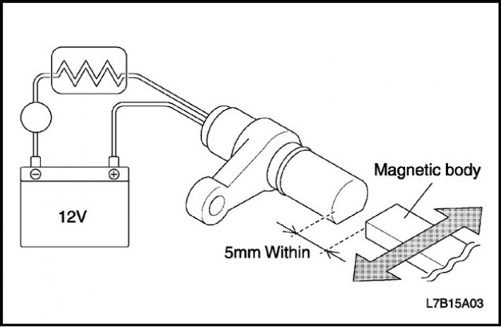
Action: If a fault is detected during the inspection, replace the primary or secondary shaft speed sensor.
Gearbox range switch
- Disconnect the automatic transmission range switch connector and check the circuits of each range for open circuits, according to the diagram provided.
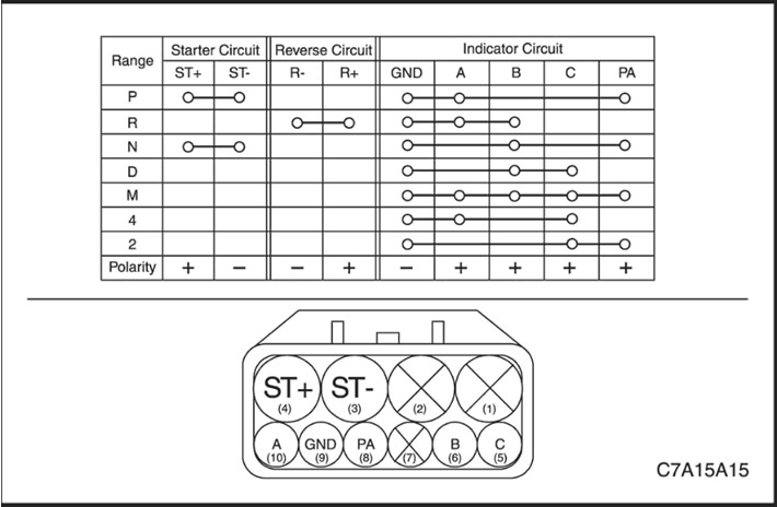
Action: If a malfunction is detected during the inspection, replace the automatic transmission range switch.
Gearbox fluid temperature sensor
- Check the resistance between the terminals of the transmission fluid temperature sensor at 10°C (50°F) and at 110°C (230°F).
|
Norm
|
10°C (50°F)
|
110°C (230°F)
|
|
5.80~7.09 kOhm
|
0.231~0.263 kOhm
|
Action: If a malfunction is detected during the inspection, replace the transmission fluid temperature sensor.
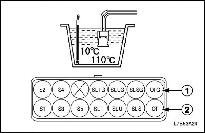
- Grounding the gearbox fluid temperature sensor
- Gearbox fluid temperature sensor signal
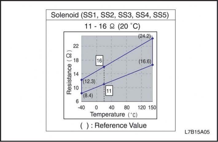
Solenoid switching valve (No. 1, No.2, No.3, No.4, No.5)
1. Check the resistance between the contacts of all switching valves and the body ground.
Action: If a fault is detected during the inspection, replace the valves.
Note:
- Recheck the resistance at 20°C (68°F) if it was not within the specified value at temperatures other than 20°C (68°F).
- At higher temperatures, the resistance value can approach infinity.
2. Check the functionality of the switching valves.
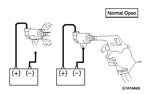
- Solenoid valve (No. 1, 4) (Normal opening type)
|
Battery power is not supplied
|
Air leak
|
|
Power is supplied from the battery
|
There is no air leakage
|
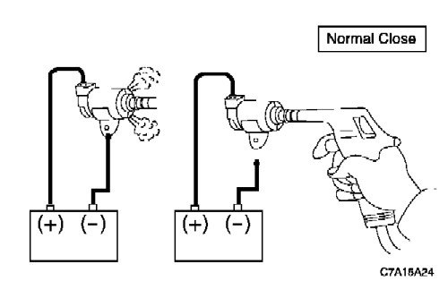
- Solenoid valve (No. 2, 3, 5) (Normal closing type)
|
Battery power is not supplied
|
There is no air leakage
|
|
Power is supplied from the battery
|
Air leak
|
Action: If a fault is detected during the inspection, replace the valves.
Note: Do not damage the solenoid valve filter.
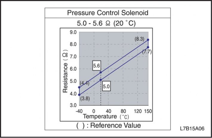
Solenoid pressure regulator valve
- Check the resistance between the contacts of all pressure regulating valves.
Action: Replace the valve block assembly. (Separate replacement of the solenoid valve is not permitted)
Note:
- Recheck the resistance at 20°C (68°F) if it was not within the specified value at temperatures other than 20°C (68°F).
- At higher temperatures, the resistance value can approach infinity.
Repairs performed on the vehicle (table)
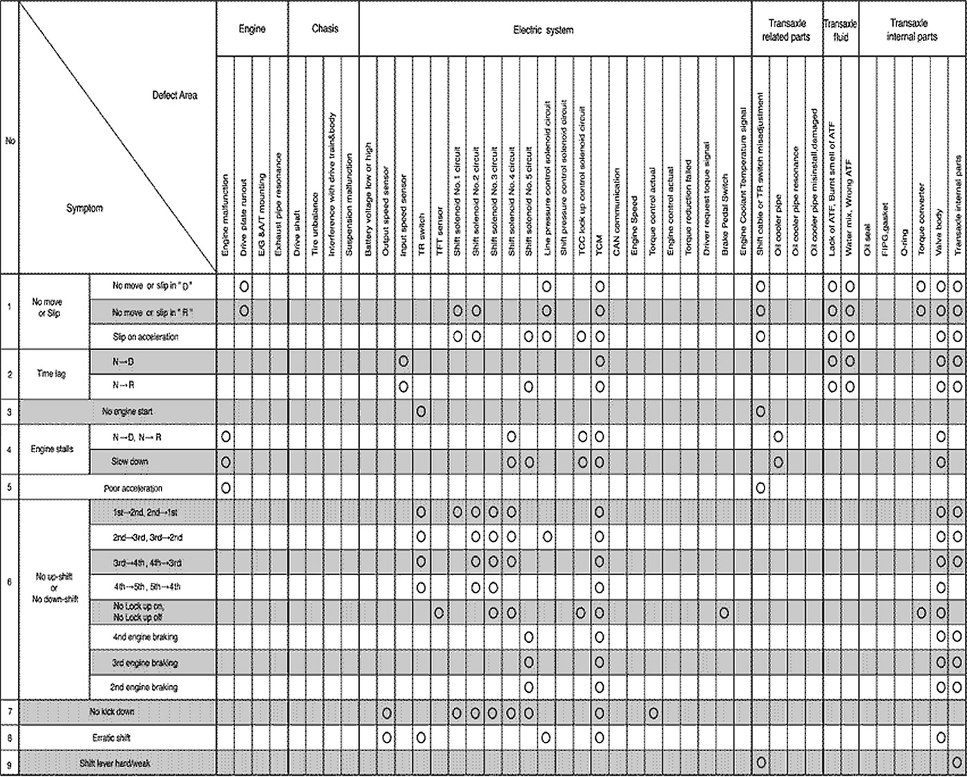
Open large image in new tab →
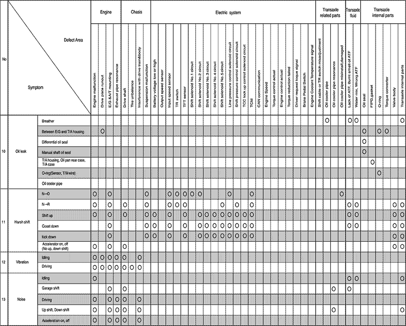
Open large image in new tab →
The material was created based on information from the website «chevyman.ru»