
ChevyMan.ru
Mazda Mitsubishi Toyota Land Rover Honda Kia Nissan
English Русский
Български
Беларускі
Український
Српски
Hrvatski
Română
Polski
Slovenský
Magyar
|
Articles | Sitemap | Contacts |


Home   Aveo   Captiva   Cruze   Lacetti   Lanos   Niva   Tahoe   Others  
Tahoe 2 and 3 (2000-2014) Tahoe 1 (1992-2000)
  • Home
  • Tahoe
  • 2 (2000-2014)
  • Chassis
  • Brake system
  • System pressure modulator valve

System pressure modulator valve (Chevrolet Tahoe 2)

            0

Contents: Removal ↧ Installation ↧

Removal


Caution: To prevent loss of brake fluid and dirt from entering the system, plug any open holes.


1. Raise the vehicle and place safety posts under the frame.

2. Remove dirt from the modulator valve and fittings and brake pipes.

3. Disconnect the brake control unit wiring connector.

Caution: Mark the brake pipe installation locations on the pressure modulator valves.


Models with VSES system (w/JL4)


4. Disconnect the brake pipe support clip (1) from the frame.
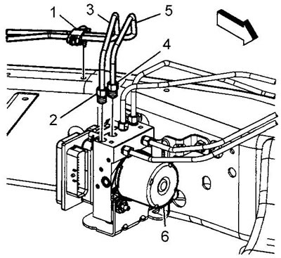
4. Disconnect the brake pipe support clip (1) from the frame.


5. Unscrew the nuts (2) and (4) of the rear brake pipes to the modulator valve (6). Tightening torque 18 Nm.

6. Remove the rear brake pipes (3) and (5) from the valve (6).

7. Unscrew the nut (7) securing the front brake pipe to the modulator valve (6).
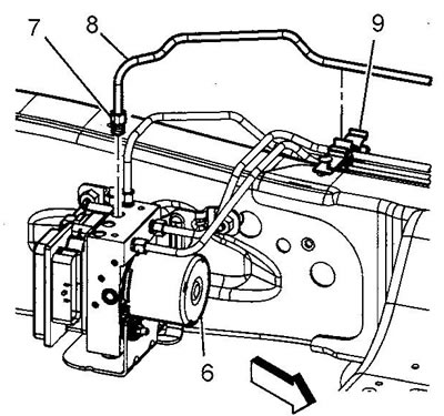
7. Unscrew the nut (7) securing the front brake pipe to the modulator valve (6).


8. Remove the front brake pipe (8) from the valve (6) and clip (9).


9. Unscrew the nuts (10) of the front brake pipes to the valve (6). Tightening torque 18 Nm.
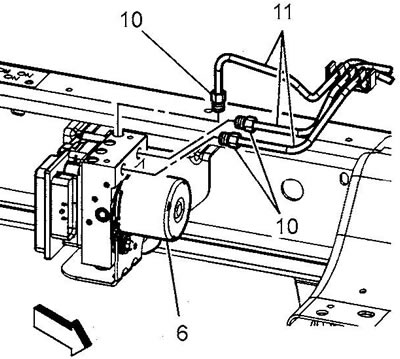
9. Unscrew the nuts (10) of the front brake pipes to the valve (6). Tightening torque 18 Nm.


10. Remove the front brake pipes (11) from the valve (6).

11. Loosen the bolts securing the modulator valve bracket to the frame. Tightening torque 22 N·m.
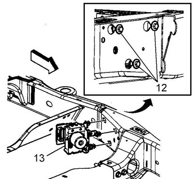
11. Loosen the bolts securing the modulator valve bracket to the frame. Tightening torque 22 N·m.


12. Slide the bracket and valve toward the front of the vehicle and remove the assembly from the vehicle.

13. If necessary, remove the control unit from the valve.

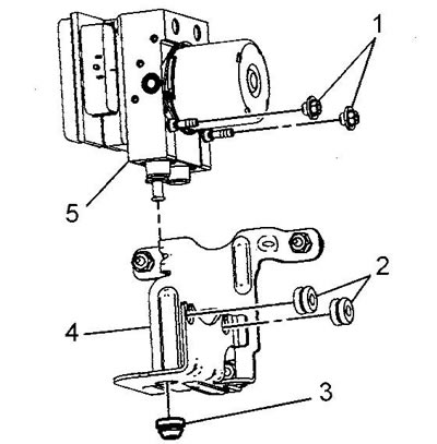
14. To disconnect the bracket (4) from the valve (5), unscrew the fastening nuts (1). Tightening torque 9 Nm.
14. To disconnect the bracket (4) from the valve (5), unscrew the fastening nuts (1). Tightening…


15. Carefully remove the valve from the front rubber supports (2) of the bracket.


Caution: Do not lift the valve using the lever.


16. Remove the valve from the lower rubber support (3).

17. Installation is carried out in reverse order. After installation, bleed the brake system.

Models without VSES system (w/o JL4)


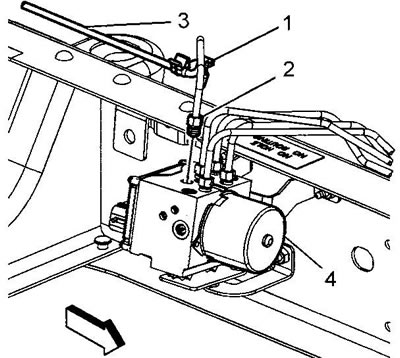
4. Disconnect the brake pipe support clip (1) from the frame.

5. Unscrew the nut (2) securing the rear brake pipe to the modulator valve (4). Tightening torque 18 Nm.
5. Unscrew the nut (2) securing the rear brake pipe to the modulator valve (4). Tightening torque…


6. Remove the rear brake pipe (3) from the valve (4).

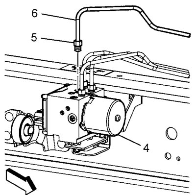
7. Unscrew the nut (5) securing the front brake pipe (6), remove the pipe from the valve. Tightening torque 18 Nm.
7. Unscrew the nut (5) securing the front brake pipe (6), remove the pipe from the valve.…


8. Unscrew the nuts (7) securing the front brake pipes. Tightening torque 18 Nm.

8. Unscrew the nuts (7) securing the front brake pipes. Tightening torque 18 Nm.
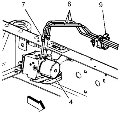

9. Remove the front brake pipes (8) from the valve (4) and the clip (9) from the frame.


10. Loosen the bolts (1) securing the modulator valve bracket to the frame. Tightening torque 22 Nm.
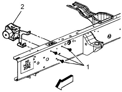
10. Loosen the bolts (1) securing the modulator valve bracket to the frame. Tightening torque 22 Nm.


11. Remove the modulator valve.

12. If necessary, remove the control unit from the valve.

13. To disconnect the bracket (4) from the valve, unscrew the valve mounting bolt (1). Tightening torque 10 Nm.
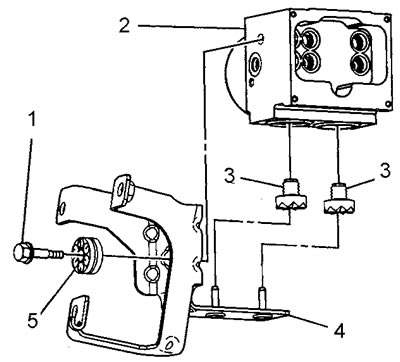
13. To disconnect the bracket (4) from the valve, unscrew the valve mounting bolt (1). Tightening…


14. Remove the modulator valve from the bracket.

15. Remove the rubber supports (3) from the valve (2) and/or bracket (4).

Installation


16. Installation is carried out in reverse order. After installation, bleed the brake system.

(The article is reprinted from the website: ChevyMan)

The article was checked: Vladimir Romannikov
This article is available at russian, bulgarian, belarusian, ukrainian, serbian, croatian, romanian, polish, slovak, hungarian

Share information:

Previous articles
Tahoe 2 and 3: Brake system
Next articles

Manual bleeding of the brake system
Automated bleeding of the brake system
Controllability improvement systems
Electronic brake control unit
Front wheel speed sensor
Rear wheel speed sensor
Rear wheel speed sensor synchronizing ring
Traction control switch


See similar articles on the topic of Chevrolet cars:
Checking the pressure in the fuel system Chevrolet Aveo T300 (2012-2018)
Relieving pressure in the fuel supply system Chevrolet Captiva 1 (2006-2018)
Checking the pressure in the fuel system Chevrolet Cruze 1 (2008-2016)
Removal the valve and vacuum reservoir of the variable intake tract system Chevrolet Lacetti 1 (2002-2009)
Checking the pressure in the engine fuel system Chevrolet Lanos T150 (2002-2009)
Electronic anti-theft system Chevrolet Niva 1 (2002-2016)
Removal and installation the oil filter flange and pressure regulator valve Chevrolet Lumina 1 (1989-1994)
Link in different formats to this page


Visitor comments

No comments yet


How much will 43 + 14 =


Tahoe 2 and 3 (2000-2014) 
  • General information
  • Vehicle characteristics
  • Vehicle device
  • Manual
  • Maintenance
  • Power unit
  • Engine repair
  • Engine overhaul
  • Cooling system
  • Injection and control system
  • Exhaust system
  • Engine electrical equipment
  • Transmission
  • Automatic gearbox 4L60, 4L65, 4L70
  • Automatic gearbox 6L50, 6L80, 6L90
  • Transfer case
  • Drive shafts and cardan
  • Front drive axle
  • Rear drive axle
  • Chassis
  • Car suspension
  • Steering
  • Brake system
  • Body (until 2007)
  • Exterior (external elements)
  • Interior (internal elements)
  • Doors, locks and windows
  • Heating and air conditioning
  • Security System (SRS)
  • Body (since 2007)
  • Exterior (external elements)
  • Doors, locks and windows
  • Interior (internal elements)
  • Electrical equipment
  • Electrical appliances (until 2007)
  • Lighting and lamps (until 2007)
  • Audio system (until 2007)
  • Electrical appliances (since 2007)
  • Lighting and lamps (since 2007)
  • Audio system (since 2007)
  • Wiring diagrams (2000-2005)
  • Wiring diagrams (2005-2007)
  • Wiring diagrams (since 2007)


Tahoe 1 (1992-2000) 
  • General information
  • User manual
  • Maintenance
  • Power unit
  • Engine in a car
  • Engine removed
  • Cooling system
  • Heating and air conditioning
  • Fuel and exhaust systems
  • Decreased toxicity
  • Transmission
  • Manual gearbox
  • Automatic gearbox
  • Transfer case
  • Clutch and drive shafts
  • Chassis
  • Brake system
  • Car suspension
  • Steering
  • Body
  • Repair of body elements
  • Electrical equipment
  • Engine electrics
  • Equipment and devices
  • Electrical circuits


ChevyMan.ru © 2017-2026 · Mobile version · Feedback · Site search · Interesting to read · Sitemap: EN BG BY UA RS HR RO PL SK HU

Aveo 2003-2008 · Aveo 2006-2011 · Aveo 2012-2018 · Captiva 2006-2018 · Cruze 2008-2016 · Lacetti 2002-2009 · Lanos 2002-2009 · Niva 2002-2016 · Tahoe 1992-2000 · Tahoe 2000-2014 · Lumina 1 1989-1994 · Trailblazer 1 2001-2008 · Orlando 1 2010-2018 ·
🛡️ For your security and to improve our service, this site uses cookies. You can disable them in your browser.