


Contents: Removal ↧ Installation ↧
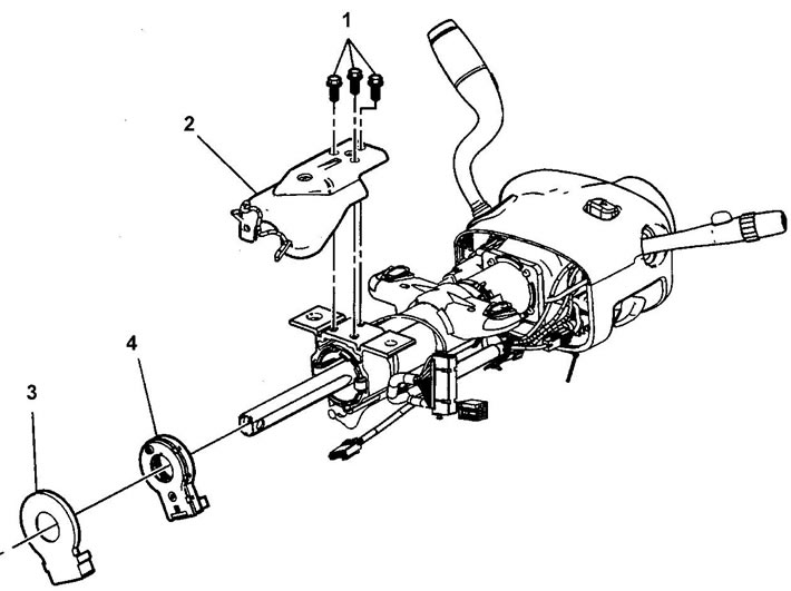
Steering wheel position sensor. 1 - bolt, 2 - steering column bracket, 3 - sensor fixing clip, 4 - steering wheel position sensor.
Removal
Caution: Identify the sensor type using the illustrations provided BEFORE removing the sensor from the steering column. If the sensor does not have marks indicating the relative position of the rotor and housing, apply them BEFORE removing the sensor.
1. Determine the type of sensor installed.
2. Determine the orientation of the sensor:
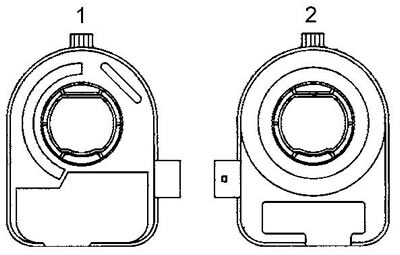
Type 1
From the operator's point of view, the "forward" position of the sensor is defined as the connector on the right (1), and the "backward" position is the connector on the left (2).
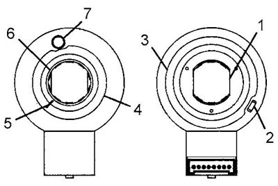
Type 2
From the operator's point of view, the forward position of the sensor is defined as:
- a porous ring is visible (4);
- the hole (7) of the centering pin is visible;
- the rotor (6) of the sensor is located flush with the housing;
- marks (5) of the relative position of the rotor and the housing are visible.
From the operator's point of view, the "back" position of the sensor is defined as:
- rotor chamfers (1) are visible;
- a porous ring is visible (3);
- the eye (2) of the sensor orientation at the installation site is visible;
- the wiring connector terminals are visible.
Type 3
From the operator's point of view, the forward position of the sensor is defined as:
- the raised edge of the rotor is visible (5);
- marks (4) of the relative position of the rotor and the housing are visible;
- the hole (3) of the centering pin is visible.
From the operator's point of view, the "back" position of the sensor is defined as:
- rotor chamfers (1) are visible;
- the eye (2) of the sensor orientation at the installation site is visible.
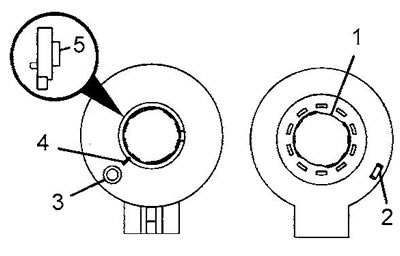
Type 4
From the operator's point of view, the forward position of the sensor is defined as:
- the raised edge of the rotor is visible (4);
- marks (3) of the relative position of the rotor and the housing are visible;
- the hole (2) of the centering pin is visible.
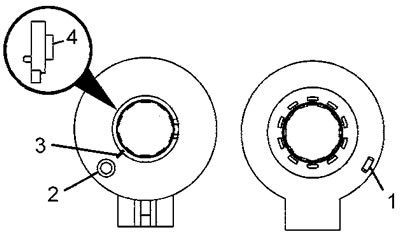
From the operator's point of view, the "back" position of the sensor is determined by the presence of the mounting lug (1). This type of sensor has no flats on the rotor.
Type 5
From the operator's point of view, the forward position of the sensor is defined as:
- the rotor (4) is flush with the housing;
- the hole (2) of the centering pin is visible. Remember the position of the hole.
- marks (3) of the relative position of the rotor and the housing are visible.
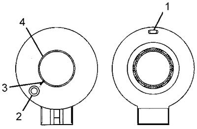
From the operator's point of view, the "back" position of the sensor is determined by the presence of the mounting lug (1). This type of sensor has no flats on the rotor.
Type 6
From the operator's point of view, the forward position of the sensor is defined as:
- the rotor (5) is flush with the housing;
- the hole (3) of the centering pin is visible. Remember the position of the hole;
- marks (4) of the relative position of the rotor and the housing are visible;
- a porous ring (6) is visible.
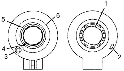
From the operator's point of view, the "back" position of the sensor is determined by the presence of the mounting lug (2), and the rotor flats (1) are visible.
3. Disconnect the sensor wiring connector.
4. Remove the sensor from the adapter and bearing assembly.
Installation
Caution: If installing an old sensor, align the relative position marks of the rotor and sensor housing before installation. The marks must remain aligned until the sensor is fully installed. If installing a new sensor, do not remove the sensor centering pin until the sensor is fully installed. If the new sensor does not have a centering pin, re-order the sensor.
Note: There is no need to center the old type 1 sensor.
1. Orient the sensor correctly, align the sensor with the steering shaft and install it onto the adapter and bearing assembly.
2. Connect the sensor wiring connector.
[The article is based on data from the website: CHEVYMAN.ru]