
Removal and installation
Note:
- Before carrying out any work, disconnect the cable from the negative terminal of the battery.
- Installation is carried out in the reverse order of removal.
1. Jack up the vehicle and place safety stands under the frame.
2. Remove the automatic transmission pan.
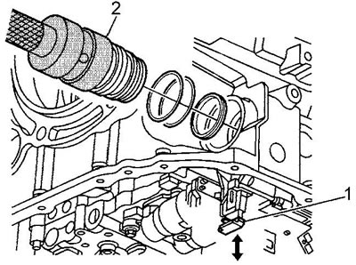
3. Disconnect the gearbox connector.
- a) Unlock the connector lock (1).
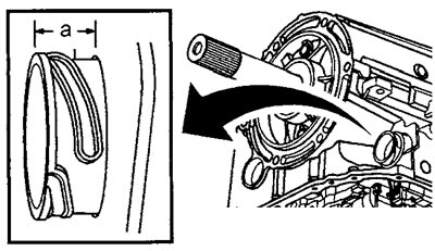
- b) Disconnect the connector (2) using a special puller and a mandrel. When installing, the width from the gearbox housing to the end surface of the connector must correspond to the nominal value. The nominal value is 14-16 mm.
 |
 |
4. Loosen the manual lock spring mounting bolt. Tightening torque 12 Nm.
5. Loosen the six valve block mounting bolts. Tightening torque 8 Nm.
Attention:
- Remove only the bolts shown in the illustration "Removing the valve block (1)".
- The order of installing the bolts is shown in the assembly drawing.
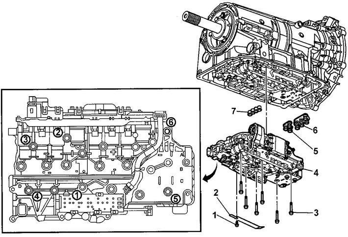
Removal the valve block (1). 1 - bolt, 2 - manual lock spring, 3 - bolts, 4 - valve block, 5, 6 - working fluid pump seal, 7 - working fluid central flow channel seal.
6. Remove the valve block assembly.
7. Remove the automatic transmission fluid pump seals.
8. Remove the seal of the central flow channel of the working fluid.
Attention: after replacing the oil seal, the settings of the adaptive automatic transmission system will be deleted.
9. Release the lock and disconnect the engine start inhibit switch connector.
10. Loosen the mounting bolts. Tightening torque 8 Nm.
11. Unscrew the nine valve block mounting bolts. Tightening torque 8 Nm.
Note: The order of installing the bolts is shown in the assembly drawing "Removing the valve block (2)".
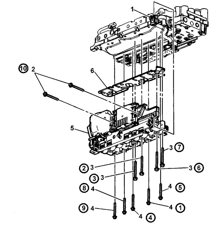
Removal the valve block (2). 1 - engine start prohibition switch connector, 2 - automatic transmission control unit mounting bolts, 3, 4 - bolt, 5 - electromagnetic valve block, 6 - filter plate.
12. Remove the electromagnetic valve block and the automatic transmission control unit.
Attention: check the condition of the filter plate board. A faulty board cannot provide the necessary filtration of the automatic transmission fluid.
13. Remove the filter plate.
14. If necessary, remove the automatic transmission control valves.
Note: The location of the solenoid valves is shown in the figure "Valve Location".
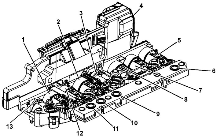
Valve arrangement. 1 - main line pressure control valve, 2 - torque converter lock-up valve, 3 - shift valve #2, 4 - control unit connector, 5 - pressure control valve #3, 6 - automatic transmission working fluid pressure sensor #5, 7 - pressure control valve #4, 8 - pressure control valve #2, 9 - automatic transmission working fluid pressure sensor #3, 10 - automatic transmission working fluid pressure sensor #1, 11 - automatic transmission working fluid pressure sensor #4, 12 - pressure control valve #5, 13 - shift valve #1.