Contents: Replacement of keys ↧ Adding keys ↧ Programming of anti-theft system… ↧ Setting up a new anti-theft system… ↧ Key encoding procedure. ↧ Anti-theft system ↧ Activation of the CTD system ↧ Locking the vehicle without… ↧ Disabling an activated… ↧ Description of the CTD scheme ↧ Vehicle Theft Deterrent (VTD) ↧ Anti-theft system controller (TDM,… ↧ Engine Control Module (ECM) ↧ Ignition key (transponder) ↧ Security indicator ↧ Immobilizing anti-theft system… ↧
Replacement of keys
If the required number of memorized master keys are not available to perform the Add Key procedure, the Key Programming procedure must be performed.
Adding keys
Important:
- To start this procedure you need to have a memorized master key.
- Up to 10 master or service keys can be programmed for one vehicle.
- This procedure is used only to add keys. This procedure does not delete previously remembered keys.
- Keys prepared for memorization must have a mechanical configuration similar to the current key.
- If more than one service key needs to be remembered, each service key must be immediately preceded by the remembered master key.
1. Using the previously memorized master key, turn on the ignition without starting the engine.
2. Turn off the ignition and remove the key.
3. Within 4 seconds, insert the key you want to remember.
Turn on the ignition without starting the engine. After this, the car will remember the new key.
Programming of anti-theft system parts
Important: After replacing the Theft Deterrent Module (TDM), the new Theft Deterrent Module setup procedure must be performed before the key programming procedure.
Setting up a new anti-theft system controller
In the main menu of the diagnostic device, select the service programming system, then follow the instructions on the screen.
Key encoding procedure.
Important: Only the master key must be used to perform the first key memorization procedure. If the service key is used first, the TDM controller will not allow additional keys to be memorized.
This procedure must be performed after replacing any of the following components:
- car keys;
- tDM controller;
- eCM controller.
Important: After replacing the TDM controller, before the key programming procedure, it is necessary to perform the procedure for setting up the new anti-theft system controller.
In the main menu of the diagnostic device, select the service programming system, then follow the instructions on the screen.
Anti-theft system
The content theft deterrent (CTD) system, when activated, is designed to help prevent theft of property from the vehicle by sounding an intermittent horn and flashing the exterior lights for approximately 30 seconds when unauthorized entry to the vehicle is detected. However, the CTD system does not affect engine starting.
When the CTD system is activated, one of the following actions is considered unauthorized access.
- Opening the rear compartment without using the remote control locking system.
- Open any door without unlocking it using the remote control for locks.
The system consists of the following parts:
- body controller;
- door opening switches;
- rear compartment door opening switch.
Activation of the CTD system
Important: The content theft deterrent (CTD) system can be activated with the windows or roof open.
To activate the system, you need to do the following.
1. Turn off the ignition.
2. Get out of the car.
Important: The system will not activate if the doors are locked manually. To activate the CTD system, you must use the remote control for the locks.
3. Lock the doors by pressing the LOCK button on the remote control. The system will enter the arming delay mode and will not start the arming timer until all doors are closed. The security indicator will flash rapidly, the CTD system is in the open state at this time. The CTD system will enter the locked state when the last door is closed.
In the locked state, the security indicator lights continuously. If the LOCK button is pressed after all the vehicle doors are closed, the open state is skipped and the system will go directly to the locked state with the security indicator lights continuously.
4. The system will activate approximately 30 seconds after entering the locked state. When the indicator starts to flash slowly, the system is activated. Otherwise, if you press the LOCK button on the remote control again, the system will activate immediately, skipping the 30-second delay.
Locking the vehicle without activating the CTD system.
The vehicle can be locked without activating the Content Theft Deterrent (CTD) system by manually locking the vehicle doors.
Disabling an activated system/turning off the alarm
If the system was activated using the remote control, it must be turned off.
Important: Manually unlocking the doors does not cancel the CTD activation mode. Also, disconnecting the battery or removing the fuses does not cancel the activation mode because the Body Control Module (BCM) stores the CTD status in memory.
To disable the CTD system, you must perform the following steps.
1. Press the UNLOCK button on the remote control.
2. Insert a valid key into the ignition and start the engine.
Description of the CTD scheme
Below is a description of all the components used in the Containment Theft Deterrence (CTD) system.
Body Control Module (BCM)
The CTD system is an internal function of the body control module (BCM) that uses data received via a serial communication line and input signals from various switches to perform CTD functions.
When the BCM detects unauthorized access, it will sound the horn and turn on the exterior lights.
When the BCM detects unauthorized access, it first enters the deterrent mode. The deterrent function commands short beeps with an audible signal. If unauthorized access continues after 10 seconds, the BCM enters the alarm mode. An intermittent audible signal is emitted and the lights flash for 30 seconds. After the 30-second alarm period, there is a 10-second pause. The system then re-arms.
Door opening switches
In the CTD system, door release switches in the door frames are used as one of the methods to activate the alarm.
The BCM monitors all door open switches via discrete inputs from each open switch. If the BCM receives a short to ground signal from a door open switch while the CTD system is active, the BCM activates an alarm.
Input signals
The BCM monitors the following input signals:
- driver and passenger door opening switches;
- rear compartment door opening switch.
- buttons LOCK and UNLOCK buttons on the control panel; internal function of BCM controller;
- key Code Status - The BCM uses the key code status to disable the system or stop the alarm when the correct vehicle key is used to start the engine.
Output signals
BCM controls the following devices:
- horn relay;
- exterior lights.
Vehicle Theft Deterrent (VTD)
The vehicle theft deterrent (VTD) functions are performed by the theft deterrent module (TDM) and the engine control module (ECM). When the ignition key is inserted into the ignition lock cylinder and the ignition is turned on, the transponder built into the head of the key is energized by the excitation coil located around the ignition lock cylinder. This excitation coil is part of the TDM. When energized, the transponder transmits a signal containing a unique value that is received by the TDM. The TDM then compares this value with a value stored in memory. If the values match, the TDM transmits a fuel enable password over the serial link to the ECM. If the transponder's unique value is incorrect, the TDM transmits a fuel inhibit password to the ECM. It is important to note that although the password is called fuel enable/inhibit, it may also disable the starter to prevent the engine from starting.
When the ECM receives a fuel enable password from the TDM, the ECM sends a password request. The ECM transmits this password request back to the TDM over the serial link. Both the ECM and the TDM perform calculations on this request. If the calculated response from the TDM matches the calculation performed in the ECM, the ECM allows the engine to start.
The VTD system consists of the following components:
- theft Deterrent Controller (TDM);
- Engine Control Module (ECM)
- ignition key (transponder);
- safety indicator.
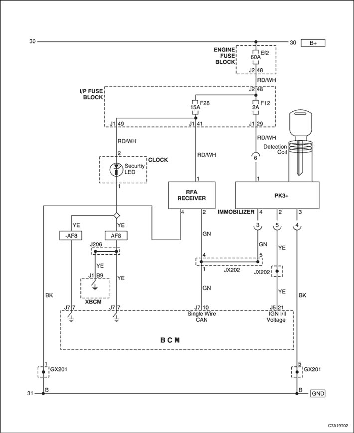
Anti-theft system controller (TDM, immobilizer)
On vehicles with steering column-mounted ignition switches, the exciter is built into the theft deterrent controller (TDM), which is located in the steering column. The TDM can store up to 10 keys (transponder values).
The TDM controller uses the following input signals: battery voltage, ignition on voltage and ground circuit. The anti-theft system controller controls the following outputs:
- password exchange and challenge/response with the engine control module (ECM).
When the ignition key is inserted into the ignition lock cylinder and the ignition is turned on, the transponder built into the key head is energized by the excitation coils located around the ignition lock cylinder. When energized, the transponder transmits a signal containing a unique value that is received by the anti-theft alarm controller. The anti-theft alarm controller then compares this value with the memorized key code stored in memory. The anti-theft alarm controller performs one of the following functions:.
- If the transponder value matches the value stored in the TDM memory, the TDM controller transmits a fuel enable command to the ECM via the serial communication line.
- If the transponder's unique value does not match the value stored in the TDM, the TDM sends a fuel inhibit command to the ECM via the serial communication line.
- If the TDM controller cannot obtain the transponder value in the ignition key, no message will be sent to the ECM.
Engine Control Module (ECM)
When the engine control module (ECM) receives a fuel enable command from the theft deterrent module (TDM), the ECM generates a password request. The ECM transmits this password request back to the TDM over a serial link. Both the ECM and TDM perform calculations on this request. If the calculated response from the TDM matches the calculation performed in the ECM, the ECM enables the engine to start.
The ECM prohibits the vehicle engine from starting if one of the following conditions is detected.
- The fuel enable password is invalid.
- The TDM controller has transmitted a fuel supply prohibition password.
- No password received - connection with TDM controller broken.
- The TDM controller's calculated response to the password request does not match the calculation performed in the ECM.
Ignition key (transponder)
The ignition key for vehicles equipped with the Passkey III+ (PK3+) immobilizer system is a standard ignition key with a transponder located in the plastic head of the key. The transponder value is permanent and cannot be changed. The vehicle theft deterrent (VTD) system uses the ignition key transponder value to determine that a valid ignition key is being used to start the engine. There are approximately 3 trillion possible transponder values.
Fleet keys provide full access to the vehicle, just like the master key. However, unlike the master keys, of which only 10 can be memorized on a single vehicle, there is no limit to the number of fleet keys that can be memorized on a single vehicle. Fleet keys are only used on vehicles configured for use in police fleets.
- Starting the car engine.
- Locking/unlocking all doors and the rear compartment.
- Locking/unlocking all luggage compartments.
Security indicator
The Theft Deterrent Module (TDM) can command the clock to turn on the security indicator only when the ignition switch is in the ON position. The TDM commands the security indicator to turn on whenever a malfunction is detected in the VTD system and the engine is inhibited from starting.
Immobilizing anti-theft system diagram