
2. Set the wheels to the straight ahead position. Lock the steering wheel.
3. Raise one side of the car so that the wheel is about 2.5 cm off the ground.
4. Install a dial indicator, the leg of which rests against the outer edge of the wheel. Rock the wheel slightly back and forth, read the dial indicator. The indicator reading should not exceed 2.5 mm. If the play in the steering exceeds the norm, check the steering rod joints. Replace the connections with noticeable play.
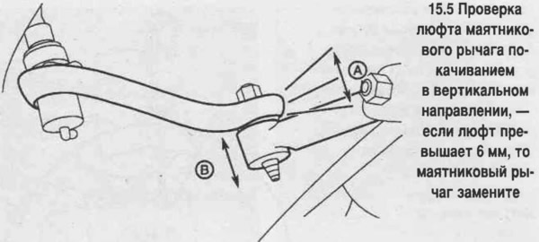
5. Raise the vehicle and place it on stands. With a force of 10 kgf, swing the pendulum lever in the vertical direction on the side where the main rod is attached. Measure the total play of the lever stroke (see photo). If the play exceeds 6 mm, replace the pendulum arm.
6. Check the condition of the ball joint boots, the tightening of the ball joint nuts and the presence of deformations or damage on the rods.
Lateral traction
7. Loosen the wheel nuts, lift the car and place it on stands.
Set the car's parking brake. Remove the wheel.
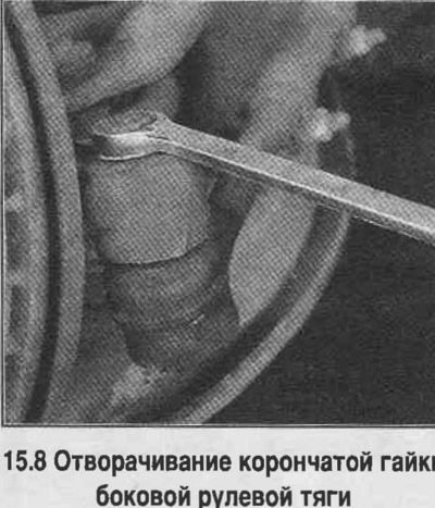
8. Unpin and release (do not turn away completely) ball joint nut (see photo).
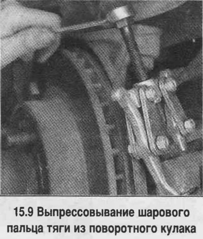
9. Press the tie rod ball pin out of the steering knuckle using a puller (see photo). Loosen the castle nut and disconnect the tie rod end from the steering knuckle eye.
10. Unscrew the nut securing the inner part of the side rod to the main rod. Disconnect the side rod from the main rod by pressing out the ball pin.
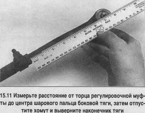
11. If the inner or outer parts of the lateral rod are replaced with new ones, then measure the distance from the end of the adjusting sleeve to the center of the ball pin (see photo). Loosen the clamps of the adjusting sleeve and unscrew the tip (the outer part of the side rod.
12. Lubricate the threaded part of the tie rod end. Screw the tie rod end into the adjusting sleeve and set the distance from the end of the pipe sleeve to the ball joint pin measured before disassembly. Do not tighten the sleeve clamps.
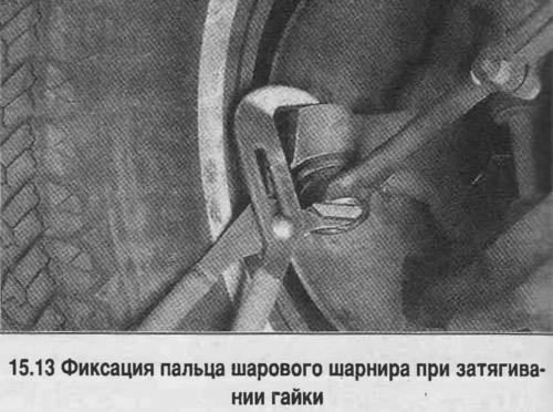
13. To install the lateral tie rod, connect the tie rod end to the steering knuckle and tighten the castle nuts. Tighten the nuts to the specified torque and secure with a new cotter pin. If the ball joint pin rotates when tightening the nut, press it against the conical part of the steering knuckle eye (see photo). If necessary, tighten the nut to align the slot in the nut with the hole in the hinge pin.
14. Insert the inner rod pivot pin into the main rod until it stops. Tighten the nut and tighten to the specified torque.
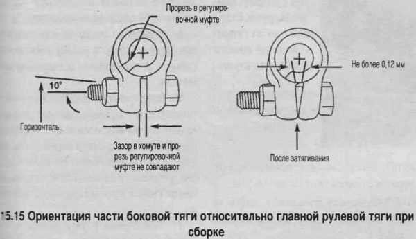
15. Tighten the clamp nuts. The bolt should be set to a position close to horizontal, and the slot in the adjusting sleeve should be aligned with the gap in the clamp (see photo).
16. Install the wheel, remove the car from the stands and tighten the wheel nuts. Check and, if necessary, adjust the wheel alignment angles at a car service center.
Pendulum lever
17. Raise the vehicle and place it on stands. Set the parking brake.
18. Loosen, but do not remove, the nut securing the pendulum arm to the main steering rod.
19. Press the pendulum arm out of the main steering rod using a two-jaw puller. Unscrew the nut.
29. Loosen the bolts securing the pendulum arm to the frame.
21. When installing, tighten the swing arm mounting bolts to the frame to the specified torque.
22. Insert the pendulum joint pin into the main steering rod and tighten the nut. Tighten the nut to the specified torque. If the ball joint pin rotates when tightening the nut, press it against the conical part of the steering knuckle eye.
Main steering rod
23. Raise the vehicle and place it on stands. Set the parking brake.
24. Disconnect the inner parts of the lateral rods from the main steering rod.
25. Disconnect the main steering rod from the steering arm.
26. Disconnect the main steering rod from the swing arm.
27. Installation is carried out in the reverse order. Tighten all nuts to the specified torque.
Bipod
28. Raise the vehicle and place it on stands.
29. Unscrew the nut of the main link ball joint pin on the steering knuckle. This nut is changed during assembly.
30. Press the pitman arm pin out of the main rod.
31. Mark the relative positions of the steering arm and the steering shaft to ensure that the steering arm is correctly aligned during assembly.
32. Unscrew the nut securing the bipod to the shaft and remove the washer.
33. Press the bipod off the shaft using a puller.
34. Check the condition of the ball joint pin threads. Inspect the seals and clean the pin threads.
35. Installation is performed in reverse order. Align the marks made when removing the bipod.
Attention! If the bipod is secured with a clamp, use a wedge to spread the jaws of the bipod clamp so that the bipod can be placed on the shaft by hand, without allowing the clamp to expand excessively. Do not press the bipod onto the shaft with hammer blows.
Shock absorber
36. Check the condition of the shock absorber, the presence of fluid leakage in it. A film of fluid may appear from under the steering gear shaft seal. If a noticeable leak is detected, replace the shock absorber.
37. Check the condition of the shock absorber bushing for signs of excessive wear. If wear is detected on the shock absorber bushing, replace it.
38. To check the shock absorber itself, disconnect it from the frame, or from the axle. Extend and compress the shock absorber as much as possible. Smooth resistance should be felt as the shock absorber moves. If there is difficulty in moving or intermittent resistance, or if the shock absorber moves with unusual noise, replace the shock absorber.
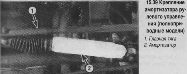
39. Unpin and loosen the shock absorber mounting nut to the main steering rod, then unscrew the nut completely (see photo). Remove the shock absorber from the main steering rod.
40. Unscrew the nut and remove the shock absorber mounting bolt, remove the shock absorber.
41 Installation of the shock absorber is performed in the reverse order.