


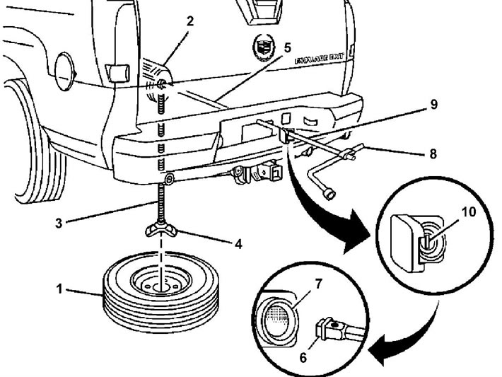
Removal the spare wheel. 1 - spare wheel, 2 - gearbox, 3 - gearbox rod, 4 - spare wheel holder, 5 - gearbox shaft, 6 - end of jack handle extension, 7 - gearbox hole, 8 - wheel brace, 9 - jack handle extensions, 10 - lock (if installed)
Note: The spare wheel removal diagram is shown in the figure "Removing the spare wheel".
1. Removing the spare wheel.
a) Remove the cover from the gearbox access hole located on the rear bumper.
Note: Some models have a lock on the spare wheel reducer that can only be removed using the ignition key.
b) Insert the end of the jack handle into the gearbox hole and lower the spare tire by turning the jack handle counterclockwise.
Note: If the spare tire does not lower, this indicates that the auxiliary spare tire locking system has been activated. To unlock the spare tire, follow the steps in the "Auxiliary Spare Tire Locking System" subsection of this section.
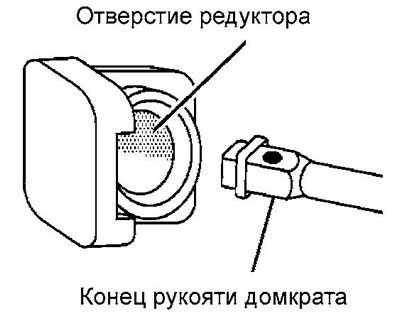
Note: Use the hook on the wheel brace to remove the spare tire from underneath the vehicle.
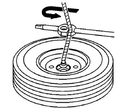
c) Remove the spare wheel holder.
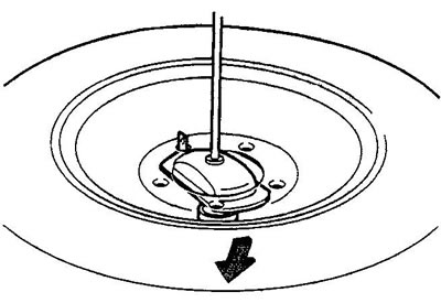
2. Install the spare wheel in the reverse order.
Additional spare wheel locking system
The spare wheel reducer is equipped with an additional spare wheel locking system designed to prevent the spare wheel from accidentally falling. For the system to operate, the spare wheel must be installed so that the valve stem faces downwards.
To release the spare tire, follow these steps:
1. Check that the end of the cable shown in the figure is visible under the bottom of the vehicle.
Note: If the cable is not visible, proceed to step 6.
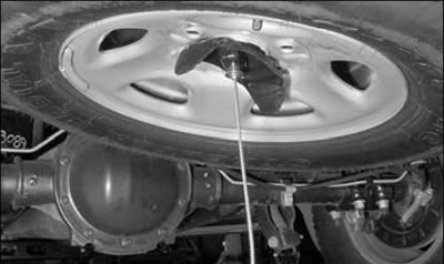
2. If the cable is visible, try tightening it first by turning the wheel wrench clockwise until you hear a double click or feel a double jump. It is impossible to overtighten the cable.
3. Loosen the cable by turning the wheel wrench counterclockwise 3-4 times.
4. Repeat the procedure at least twice. If the spare wheel drops down, proceed to the steps described in paragraph (c) of paragraph 1 of the "Spare Wheel" section.
5. Turn the wheel wrench counterclockwise until approximately 15 cm of cable appears.
6. Fold the wheel chocks and jack as shown in the figure.
Note: Make sure the structure is secure.
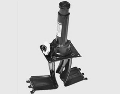
7. Assemble the jack handle (with extensions and wheel wrench), connect it to the jack and install the jack (together with wheel chocks) under the bottom of the car so that the top point of the jack is in the center of the spare wheel bracket.
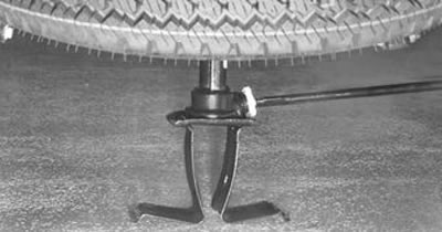
8. Turn the jack handle clockwise until the jack rests against the spare tire bracket.
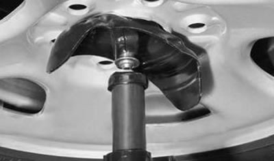
9. Continue turning the jack until the spare tire no longer rises. The additional spare tire locking system will be released when the spare tire reaches its original storage location.
Caution: After removing the spare tire, have the spare tire reducer checked by a car repair shop. It is not recommended to store the spare tire under the vehicle until the reducer malfunction has been corrected.