


Note: A special anti-stick compound is applied to the oxygen sensor thread to facilitate removal. New sensors are supplied with the compound pre-applied. When installing a working sensor, the compound must be applied independently. The tightening torque of the oxygen sensor is 42 Nm.
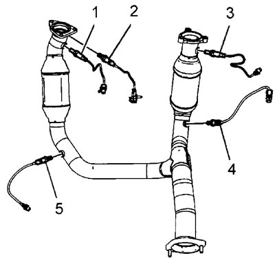
Figure "A" |
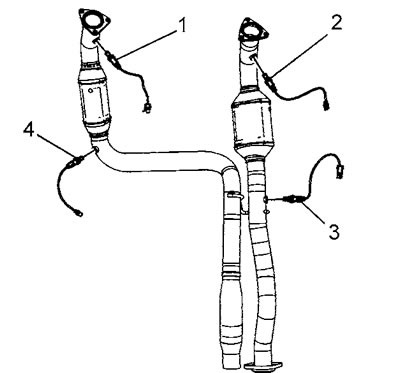
Figure "B" |
Removal and installation
Left half block, before the neutralizer (all 5.3L engines and early 6.0L engines)
1. Raise the vehicle and place safety posts under the frame
2. Disconnect the propeller shaft from the front axle final drive.
3. For vehicles with 4L60-E and 4L70-E automatic transmissions, perform the following operations; for vehicles with 6L80-E automatic transmissions, proceed to step 7.
4. Remove the wire harness connector holder.
5. Disconnect the oxygen sensor connector (2).
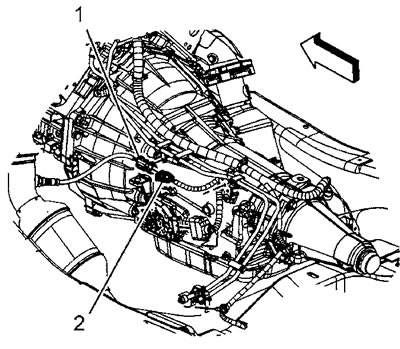
6. Remove the clip (1) securing the sensor connector to the fuel line.
7. Remove the wire harness connector holder (2).
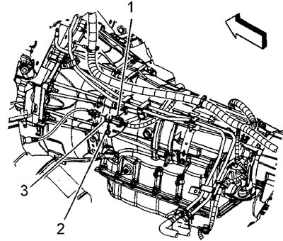
8. Release the engine wiring harness from the fuel line support clip (1).
9. Disconnect the oxygen sensor connector (3).
10. Remove the oxygen sensor (1) or (2), see figure "A".
11. Installation is carried out in reverse order.
Right half block, before the neutralizer (all 5.3L engines and early 6.0L engines)
1. Raise the vehicle and place safety posts under the frame.
2. Remove the wire harness connector holder (2).
3. Disconnect the oxygen sensor connector (7) from the engine wire harness connector (1).
4. Disconnect the oxygen sensor clip (8) from the engine wire harness.
5. Remove the oxygen sensor (3), see figure "A" above.
6. Installation is carried out in reverse order.
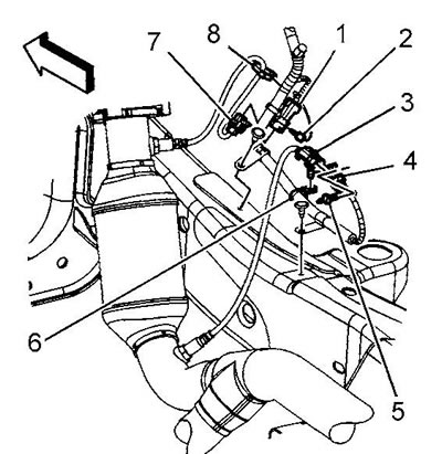
5.3L Engine, Late Models |
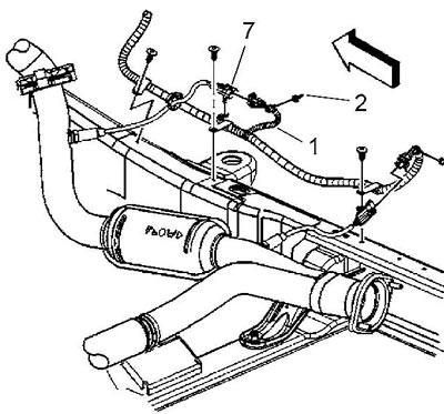
5.3L Engine, Early Models |
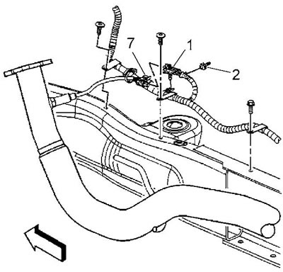
6.0L Engine, Early Models
Left half block, before the neutralizer (6.0 and 6.2L late model engines)
1. Raise the vehicle and place safety posts under the frame.
2. Disconnect the propeller shaft from the front axle final drive.
3. Remove the wire harness connector holder (2).
4. Disconnect the oxygen sensor connector (3).
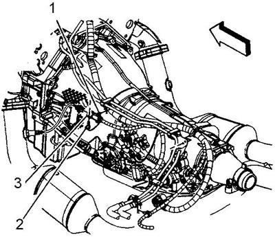
5. Remove the oxygen sensor (1), see figure "B" above.
6. Installation in reverse order.
Left half block, after the neutralizer (early model engines)
1. Raise the vehicle and place safety posts under the frame.
2. Disconnect the connector retainer.
3. Disconnect the oxygen sensor connector (2).
4. Remove the sensor.
5. Installation is carried out in reverse order.
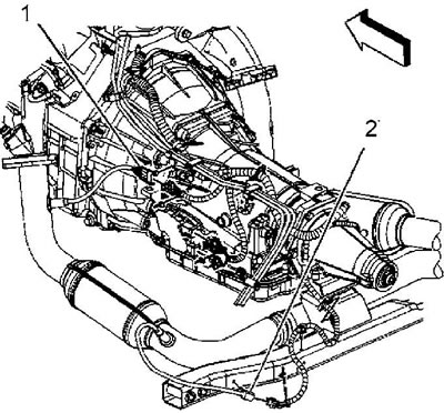
Engine 5.3 l |

Engine 6.0 l |
Left half block, after the neutralizer (late models)
1. Raise the vehicle and place safety posts under the frame.
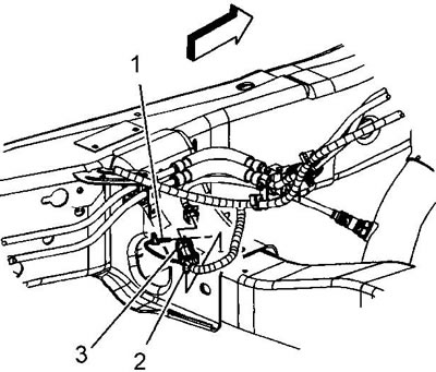
2. Remove the wire harness connector holder (1).
3. Disconnect the oxygen sensor connector (3).
4. Remove the oxygen sensor (5) or (4), see figure "A" and "B" respectively.
5. Installation is carried out in reverse order.
Right half block, before and after the neutralizer (6.0 and 6.2L late model engines)
1. Raise the vehicle and place safety posts under the frame.
2. Remove the holder (5) or (3) of the wire harness connector.
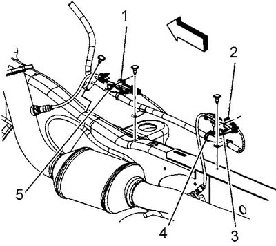
3. Disconnect the oxygen sensor connector (1) or (2).
4. Remove the oxygen sensor (2) or (3), see figure "B".
Right half block, after the neutralizer (5.3L engines and early model 6.0L engines)
1. Raise the vehicle and place safety posts under the frame.
2. Remove the holder (5) of the wire harness connector.
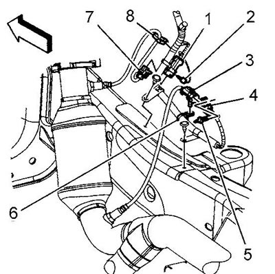
5.3L engine, late models. |
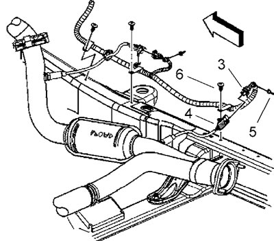
Early model 5.3L engine |
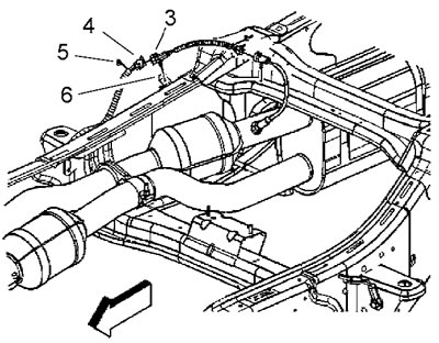
6.0L engine of early models
3. Disconnect the engine wire harness connector (4) from the connector (3).
4. Release the oxygen sensor connector from the clip (6).
5. Remove the oxygen sensor (4), see figure "A".
6. Installation is carried out in reverse order.
[The article is based on data from the website CHEVYMAN.RU]