


Contents: Before assembly ↧ Installing cylinder block plugs ↧ Installing the crankshaft ↧ Installing the piston and connecting… ↧ Further assembly ↧
Note: Installation procedures for individual parts not covered here are described above in the relevant sections. Ignore the final operations that are performed on the vehicle.
Before assembly
- Dirt will cause premature wear of the rebuilt engine, so make sure everything is assembled in a clean environment.
- Use accurate measuring instruments when assessing wear or matching parts.
- If you are installing old parts, please install them in their original locations.
- When assembling, lubricate the parts with clean engine oil. This will provide initial lubrication when the engine is first started.
Installing cylinder block plugs
Note: The cylinder block plugs removed during disassembly can be reinstalled if they are not damaged.
1. Apply a bead of sealant approximately 3 mm in diameter to the sealing washer (115) of the coolant heater.
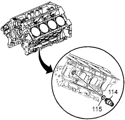
2. Install the heater (114) on the cylinder block. Tightening torque 50 Nm.
3. Apply a bead of sealant approximately 3 mm in diameter to the sealing washer of the rear drain plug of the right half block.
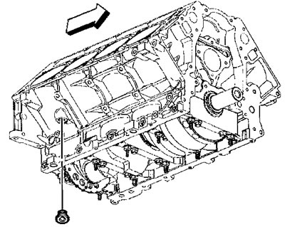
4. Install the rear drain plug of the right half-block. Tightening torque 60 N·m.
5. Apply a bead of sealant approximately 3 mm in diameter to the sealing washer (117) of the front oil gallery plug of the left half block.
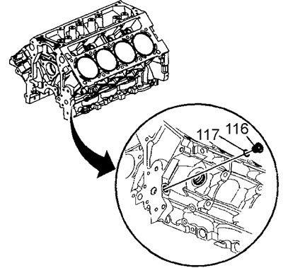
6. Install the front plug (116) of the oil gallery of the left half-block. Tightening torque 60 N·m.
7. Apply a bead of sealant approximately 3 mm in diameter to the sealing washer (113) of the rear plug of the left half-block oil gallery.
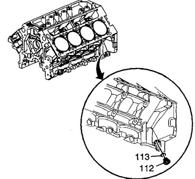
8. Install the front plug (112) of the oil gallery of the left half-block. Tightening torque 60 N·m.
9. Check the condition of the sealing ring of the rear plug of the block oil gallery. If the sealing ring is normal, it can be reused.
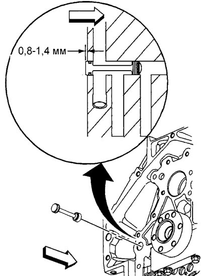
10. Lubricate the sealing ring with clean engine oil.
11. Install the sealing ring on the plug.
12. Install the rear plug so that it protrudes from the block by 0.8 - 1.4 mm.
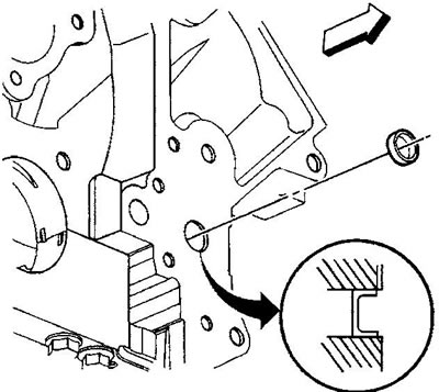
13. Apply locking adhesive to the NEW front oil gallery plug (101).
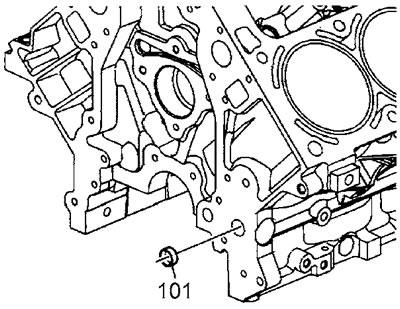
14. Install the front plug so that it is recessed 2.2-2.8 mm beyond the plane of the block.
15. Install the knock sensor (718) on the left side half-block and tighten the sensor mounting bolt (739).
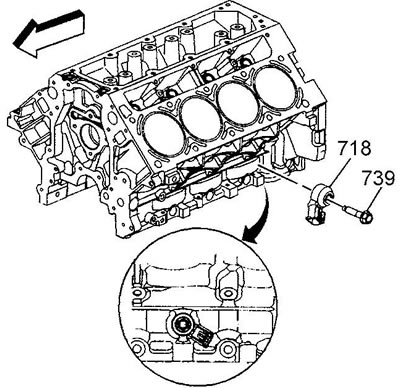
Tightening torque 20 Nm.
16. Install the knock sensor (718) of the right half-block and tighten the sensor mounting bolt (739).
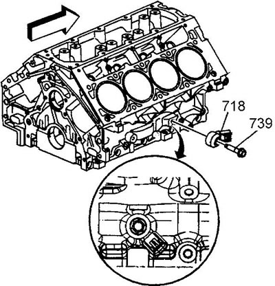
Tightening torque 20 Nm.
Installing the crankshaft
Attention:
- Main bearing clearances are critical values. Excessive main bearing clearances may adversely affect Crankshaft Position Sensor signals and/or OBDII diagnostics.
- The crankshaft main bearing caps must be installed in their proper positions and oriented correctly.
- When installing the main bearing shells, align the shell retainer with the cutout in the block and cover.
- Always install liners in pairs, do not file liners or mix liners from different pairs.
- To prevent oil leakage, install new tie bolts (M8) of the main bearing caps. The new bolts already have sealant applied.
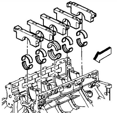
1. Install the main bearing shells into the cylinder block and bearing caps. The thrust bearing is installed on the central journal of the shaft.
2. Lubricate the bearings and crankshaft main journals with clean engine oil.
3. Install the crankshaft.
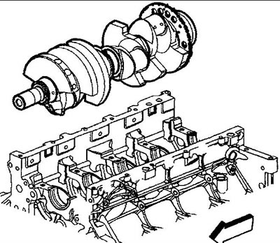
Note: Install the crankshaft carefully to avoid damaging the thrust bearing.
4. Install the crankshaft main bearing caps in their proper positions and in the correct direction.
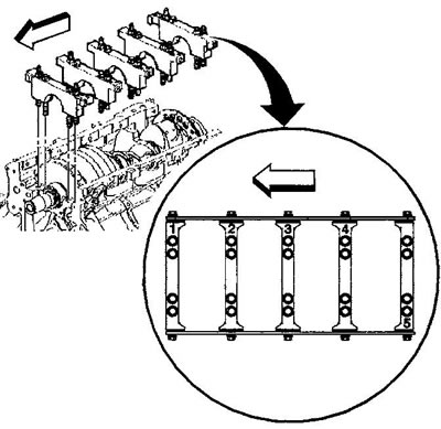
5. Install M10 bolts (129) and (128).
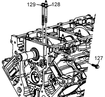
6. Use a plastic hammer to tap off the main bearing caps.
7. Install NEW M8 tie bolts (127).
8. Tighten the M10 (1-10) bearing cap bolts in the first pass in the order shown in the figure.
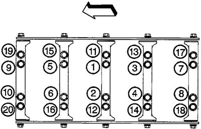
Tightening torque 20 Nm.
9. Using a plastic hammer, tap the crankshaft back and forth until it stops to properly seat the thrust bearing.
- a) Tighten the M10 bolts (1-10) completely. Tightening torque: turn by 80°.
- b) Tighten the M10 (11-20) bolts in the first pass in the sequence shown. Tightening torque 20 Nm.
- c) Tighten the M10 (11-20) bolts finally. Tightening torque: turn by 51°.
- d) Tighten the M8 tie bolts. Tightening torque 25 Nm.
Compress the bolt on 1 side of the bearing cap and then compress the bolt on the opposite side of the same bearing cap.
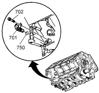
10. Install the crankshaft position sensor.
- a) Check the condition of the sensor sealing ring (750). If the ring is normal, it can be reinstalled.
- b) Lubricate the O-ring with clean engine oil.
- c) Install the sealing ring on the sensor.
- d) Install the sensor (701), turn the sensor until the sensor mounting hole is aligned with the hole for the mounting bolt in the block.
- d) Install the sensor mounting bolt (702), tighten the bolt. Tightening torque 25 Nm.
11. Measure the crankshaft axial clearance.
- a) Move the crankshaft forward or backward until it stops.
- b) Insert a feeler gauge between the working surface of the thrust bearing and the crankshaft web and measure the clearance in the bearing. Axial clearance 0.04-0.2 mm.
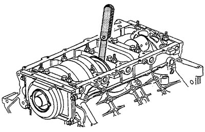
- c) If the clearance is outside the permissible limits, check the condition of the crankshaft surface on which the thrust bearing runs.
Installing the piston and connecting rod
1. Lubricate with clean engine oil:
- piston
- piston rings
- engine cylinder walls
- connecting rod bearing shells
2. Install the connecting rod bearing shells into the connecting rod and connecting rod cap.
3. Spread the oil scraper ring locks at least 25 mm apart.
4. Spread the compression ring locks 180 degrees apart.
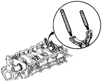
5. Screw soft metal guides into the connecting rod.
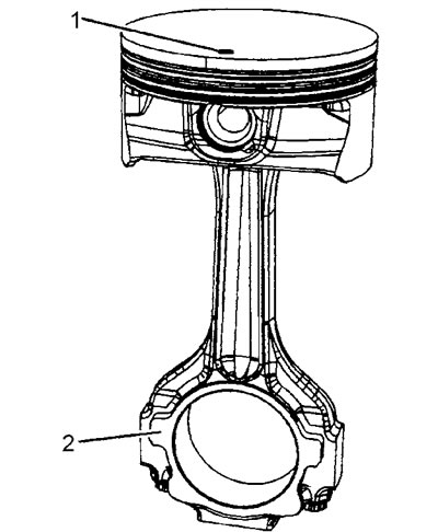
6. Check the correct assembly of the piston and connecting rod: the mark (1) on the piston head and the protrusions (2) on the connecting rod should be on the same side.
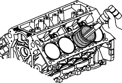
7. Use a crimping tool to compress the piston rings.
8. Install the piston and connecting rod into the appropriate cylinder. The mark on the piston should be facing the front of the engine. Press the clamp against the block and use the hammer handle to lightly tap the piston into the cylinder.
9. Unscrew the connecting rod guides.
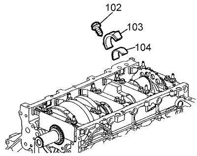
10. Install the connecting rod cap (103) together with the bearing shell (104), tighten the cap mounting bolts (102). Tightening torque: 1st pass 25 Nm; Turn the 2nd pass by 70°.
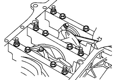
11. Measure the connecting rod side clearance and compare with the specifications.
Further assembly
Next, the engine is assembled in the reverse order of disassembly.
[The article was reprinted from the website «chevyman.ru»]