


Contents: Disassembly ↧ Checking the condition of parts ↧ Assembly of the cylinder-piston group ↧ Assembly of the crank mechanism ↧ Selection of main bearing shells… ↧ Selection of connecting rod bearing… ↧
Note: Be extremely careful not to scratch, dent or otherwise damage the crankshaft. Such damage may impair engine performance.
Disassembly
1. Remove the engine.
2. Remove auxiliary equipment: generator, power steering pump, air conditioning compressor.
3. Remove the cylinder head together with the intake and exhaust manifold.
4. Loosen the flywheel mounting screws.
5. Remove the crankshaft pulley.
6. Remove the timing belt tensioner.
7. Remove the timing belt housing elements.
8. Remove the coolant pump.
9. Remove the crankshaft toothed pulley
10. Remove the flywheel.
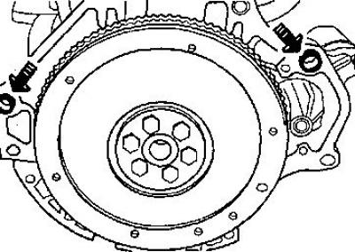
11. Remove the oil pan.
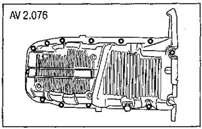
12. Remove the oil receiver.
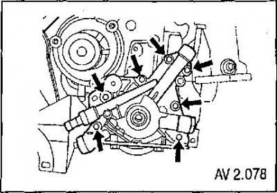
13. Remove the oil pump.
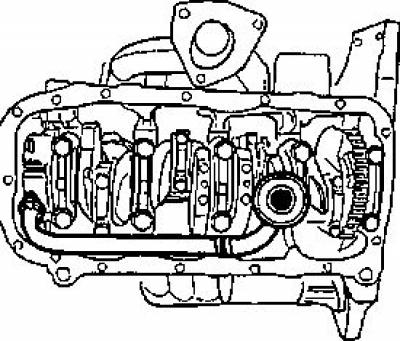
14. Unscrew the connecting rod bearing cap screws.
15. Remove the connecting rod bearing caps, marking the relative positions of the caps and connecting rods.
16. Mark the order of installation of the crankshaft main bearing caps.
17. Unscrew the crankshaft main bearing cap screws.
18. Remove the crankshaft main bearing caps.
19. Remove the crankshaft.
20. Remove the main and connecting rod bearing shells from their seats.
21. Remove the pistons with connecting rods, having first treated the upper part of the cylinder to remove carbon deposits.
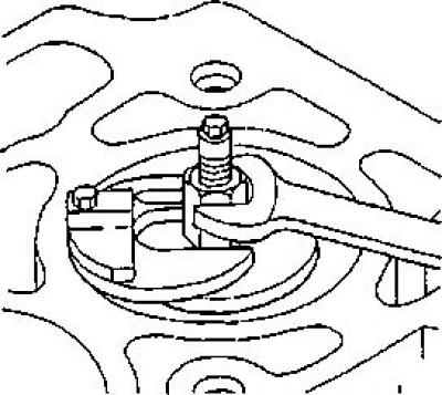
22. Remove the piston rings. Use a ring expander.
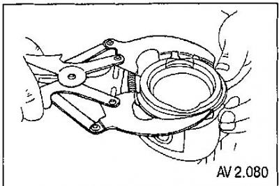
23. Remove the piston pins and separate the piston from the connecting rod.
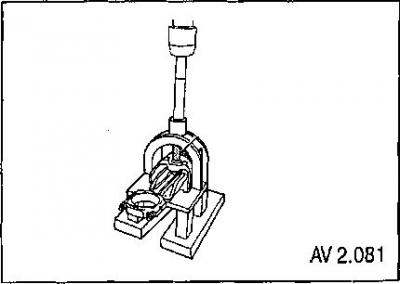
Checking the condition of parts
1. Check the connecting rods for deformation (bending and twisting). If the connecting rods are warped, replace them.
2. Check the condition of the connecting rod bearings (only to determine the operating conditions of the engine before repair, since in any case new crankshaft bearing shells should be installed).
3. Check the seat of the connecting rod bearing shells for wear.
4. Check the connecting rod upper head bore for scoring or wear.
5. Check the crankshaft journals for wear.
|
Crankshaft |
||
|
Neck of the root |
Diameter |
54.982-54.994 mm |
|
Taper (max) |
0.005 mm |
|
|
Deviation from roundness (max.) |
0.004 mm |
|
|
Main bearing clearance |
0.005 mm |
|
|
Crankshaft end runout |
0.1 mm |
|
|
Crank pin |
Diameter |
42.971-42.987 mm |
|
Taper (max) |
0.005 mm |
|
|
Deviation from roundness (max.) |
0.004 mm |
|
|
Connecting rod bearing clearance |
0.019-0.070 mm |
|
|
Connecting rod side clearance |
0.070-0.242 mm |
|
6. Check the pistons for scoring, chipping and wear.
7. Measure the piston diameter using a micrometer.
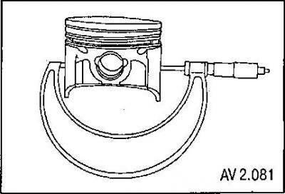
- Piston diameter - 76.470 mm
- The gap between the piston and the cylinder wall is 0.030 mm
8. Check the correct installation of the piston relative to the connecting rod (see marks).
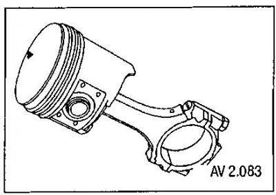
- Piston pin diameter - 18,000 mm
- Finger displacement - 0.5-0.7 mm
9. Check the cylinder block for flatness of the surface in contact with the cylinder head gasket using a ruler and feeler gauge.
10. Measure the cylinder diameter at various places using a bore gauge (at the top, middle and bottom of the cylinder, along two mutually perpendicular diameters).
Engine cylinder bore diameter:
- Diameter - 76.5 mm
- Deviations from roundness (max.) — 0.0065 mm
- Taper (max) - 0.0065 mm
11. Check the condition of the cylinder walls for protrusions, burnt-through walls, increased local wear, and scoring.
12. Check the condition of the cylinder walls for varnish and carbon deposits; if necessary, perform light honing for cleaning purposes.
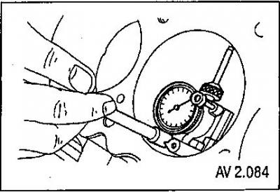
Assembly of the cylinder-piston group
1. Connect the connecting rods to the pistons so that the mark on the piston is directed towards the front of the engine (towards the timing belt).
2. Install the piston pin installation tool guide.
3. Apply a layer of clean motor oil to the pistons.
4. Install the piston pins.
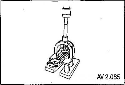
Piston pin:
- Diameter - 18,000 mm
- Finger displacement - 0.5-0.7 mm
5. Measure the gap in the new piston ring joints by installing them in the cylinder without a piston.
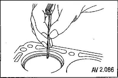
6. Measure the side clearances between the rings and the walls of the piston grooves. Based on the measurement results, if the wear of the grooves is too great, replace the pistons.
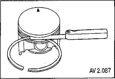
7. Install the piston rings in the sequence shown in the figure using a ring expander.
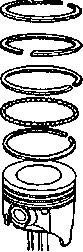
Piston rings: Lower oil scraper, Axial expander, Upper oil scraper, Lower compression, Upper compression.
|
Piston rings |
||
|
Compression, gap in the joint |
Top |
0.3 mm |
|
2nd compression |
0.3 mm |
|
|
Axial clearance in piston ring groove |
Top |
0.02 mm |
|
2nd compression |
0.02 mm |
|
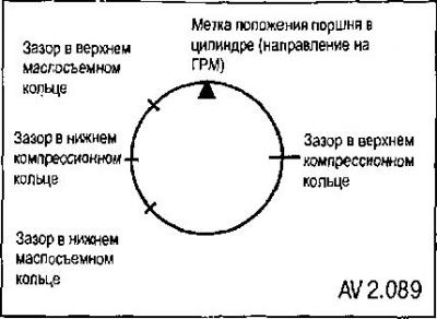
Distribute the piston ring gaps as shown in the figure.
9. Apply a layer of engine oil to the cylinder walls.
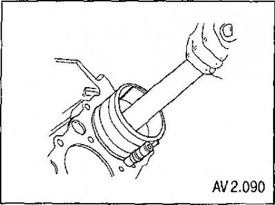
10. Install the pistons into the cylinders using a ring crimper and lightly tap with a wooden hammer handle,
Assembly of the crank mechanism
All parts must be cleaned before assembly.
1. Using a plastic gauge, determine the clearances in all crankshaft bearings. See "Selection of connecting rod bearing shells using a plastic gauge" and "Selection of main bearing shells using a plastic gauge".
2. Check the radial runout of the rear sealing journal of the crankshaft with the bearings installed.
3. Check the axial run-out of the crankshaft.
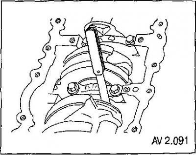
4. Check the runout of the surface of the journal of the middle main bearing of the crankshaft.
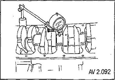
5. Apply a thin layer of engine oil to the crankshaft bearing shells.
6. Install the crankshaft.
7. Apply sealing compound to the rear main bearing cap.
8. Install the crankshaft main bearing caps Nos. 1-4.
9. Install the main bearing cap No.5. Make sure that the sealant evenly seals the joints between the cap and the cylinder block.
Note: Do not reuse old crankshaft main bearing bolts.
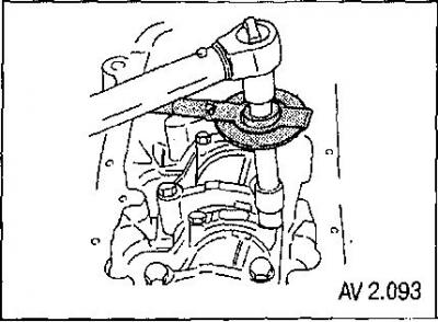
10. Tighten the crankshaft main bearing cap screws:
- tighten the screws to 50 Nm;
- tighten to an angle of 45°+15°.
11. Install the connecting rod bearing shells into the connecting rods and into the connecting rod bearing caps.
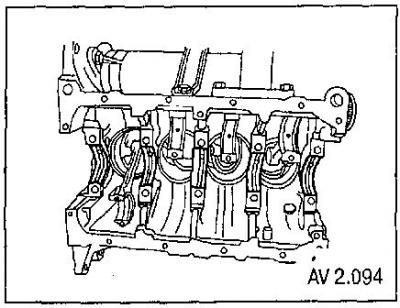
12. Install the connecting rod bearing caps.
Note: Do not reuse old connecting rod bearing cap screws.
13. Tighten the connecting rod bearing cap screws to a torque of 25 Nm.
14. Tighten the connecting rod bearing cap screws to an angle of 30° +15°.
15. Install the oil pump.
16. Tighten the oil pump screws to a torque of 10 Nm.
17. Install the oil receiver.
18. Tighten the oil receiver screws to a torque of 10 Nm.
19. Install the oil pan gasket.
20. Install the oil pan no later than 5 minutes after applying the sealant gasket.
21. Tighten the oil pan bolts to 10 Nm.
22. Install the crankshaft toothed pulley.
23. Install the rear part of the timing belt cover.
24. Tighten the rear timing belt cover screws to 10 Nm.
25. Install the automatic timing belt tensioner.
26. Tighten the timing belt automatic tensioner screw to a torque of 20 Nm.
27. Tighten the camshaft timing pulley screw to a torque of 45 Nm.
28. Install the timing belt.
29. Adjust the tension of the camshaft drive toothed belt.
30. Install the valve cover with gasket.
31. Tighten the camshaft cover screws to 10 Nm.
32. Install the lower part of the timing belt housing.
33. Tighten the timing belt cover lower part screws to 10 Nm.
34. Install the power steering pump.
35. Tighten the power steering pump screws to 25 Nm.
36. Install the upper part of the timing belt cover.
37. Tighten the timing belt cover upper part screws to 10 Nm.
38. Install the rear crankshaft oil seal using a drift.

39. Install the flywheel.
40. Tighten the flywheel mounting screws to a torque of 35 Nm.
41. Tighten the flywheel mounting screws at an angle of 30°+15°.
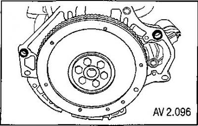
42. Install the engine into the vehicle.
Selection of main bearing shells using a plastic gauge
1. Apply a layer of engine oil to the crankshaft main bearings.
2. Install the upper and lower crankshaft main bearings.
3. Install the crankshaft.
4. Check the radial runout of the rear sealing journal of the crankshaft with the bearings installed.
5. Check the axial run-out of the crankshaft.
6. Check the runout of the journal surface of the middle main bearing of the crankshaft on the crankshaft installed on the front and rear bearings.
7. Check all clearances in the crankshaft bearings.
8. Cut plastic measuring strips of length equal to the width of the bearings. Place them along the axis between the crankshaft journals and the main bearing shells.
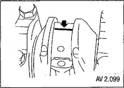
9. Install the crankshaft bearing caps.
10. Tighten the crankshaft main bearing cap screws to a torque of 50 Nm.
11. Tighten the crankshaft main bearing cap screws at an angle of 45°+15°.
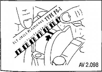
12. Remove the crankshaft main bearing caps.
13. Measure the width of the flattened part of the plastic strip using a ruler.
Selection of connecting rod bearing liners using a plastic gauge
1. Apply a layer of engine oil to the connecting rod bearing shells.
2. Install the upper and lower connecting rod bearings.
3. Install the lower connecting rod bearing shells.
4. Check the clearances in the connecting rod bearings.
5. Cut plastic measuring strips of length equal to the width of the bearings. Place them axially between the connecting rod bearing journals and the connecting rod bearing shells.
6. Install the connecting rod bearing caps.
7. Tighten the connecting rod bearing cap screws to a torque of 25 Nm.
8. Tighten the crankshaft cover screws at an angle of 30°+15°.
9. Remove the connecting rod bearing caps.
10. Measure the width of the flattened plastic layer using a ruler.
11. Compare the obtained results with the permissible values of bearing clearances.