
ChevyMan.ru
Mazda Mitsubishi Toyota Land Rover Honda Kia Nissan
English Русский
Български
Беларускі
Український
Српски
Hrvatski
Română
Polski
Slovenský
Magyar
|
Articles | Sitemap | Contacts |


Home   Aveo   Captiva   Cruze   Lacetti   Lanos   Niva   Tahoe   Others  
Tahoe 2 and 3 (2000-2014) Tahoe 1 (1992-2000)
  • Home
  • Tahoe
  • 1 (1992-2000)
  • Power unit
  • Fuel and exhaust systems
  • Throttle body (TBI module) — replacement of parts

Throttle body (TBI module) — replacement of parts (Chevrolet Tahoe 1)

            0

Contents: Fuel Flow Meter/Fuel Pressure… ↧ Nozzles ↧ Throttle Position Sensor (TPS… ↧ Fuel flow meter housing ↧
Important! It is not necessary to remove and disassemble the throttle body to replace the parts. However, for the sake of clarity, the procedures described assume that the TBI module has been removed from the vehicle.


1. Decompress the fuel system.

2. Disconnect the battery from ground.

3. Remove the air filter, adapter and gaskets.

Fuel Flow Meter/Fuel Pressure Regulator Cover Assembly


Attention! The pressure regulator is located in the fuel flow meter cover. If the flow meter or regulator fails, the entire assembly is replaced.


4. Disconnect the connectors from the injectors.

5. Unscrew the screws (see photo) and remove the lid.
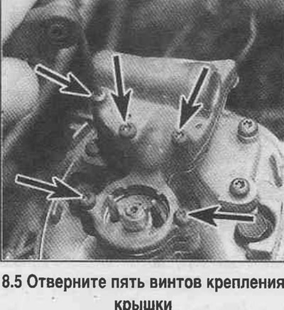
5. Unscrew the screws (see photo) and remove the lid.


6. Remove any remaining old seals (see photo).
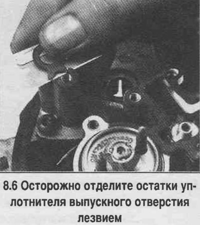
6. Remove any remaining old seals (see photo).


7. Inspect and clean the cap. Do not immerse the cap in solvent as this will damage the diaphragm and gasket of the pressure regulator.
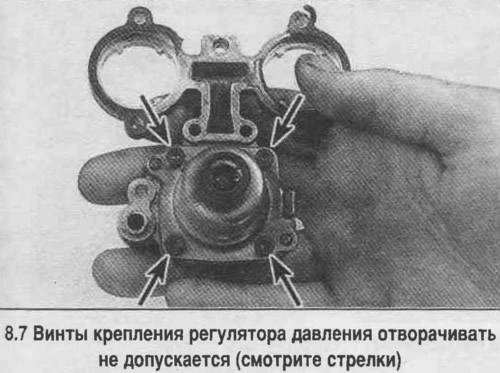


7. Inspect and clean the cap. Do not immerse the cap in solvent as this will damage the diaphragm…


Attention! It is forbidden to unscrew the 4 screws securing the pressure regulator to the cover (see photo), to avoid damage to the diaphragm under the action of the releasing regulator spring.


8. Install the unit in reverse order, replacing the gaskets and seals.

Nozzles


9. Disconnect the connectors from the injectors by squeezing the latches and pushing the connector towards you.

10. Remove the cover with the flow meter/pressure regulator.

11. Pry up and remove the nozzle (see photo).
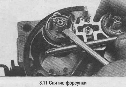
11. Pry up and remove the nozzle (see photo).


12. Remove the upper (larger) and lower (smaller) O-rings and injector filter.

13. Remove the steel washer from the injector seat.

14. Inspect the fuel injector filter. If contamination is detected, clean the fuel lines and flush the fuel tank.


15. When replacing, please note that the Model 220 TBI system injectors are not interchangeable with injectors of other systems.

16. When assembling, place the new filter on the injector nozzle (see photo).

17. Lubricate the new lower (smaller) sealing ring with automatic transmission fluid and install it into the flange seat in the injector well (see photo).

18. Install a steel washer into the nozzle (see photo).
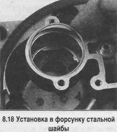
18. Install a steel washer into the nozzle (see photo).


19. Lubricate the new upper O-ring with automatic transmission fluid and install it on the steel washer (see photo).
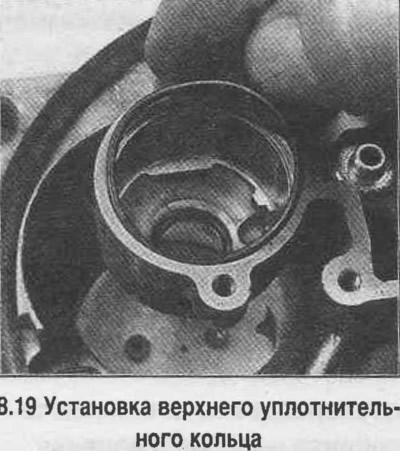
19. Lubricate the new upper O-ring with automatic transmission fluid and install it on the steel…


Caution! The washer and large sealing ring must be installed in front of the injector. Do not allow this ring to twist.


20. Install the nozzle (see photo).
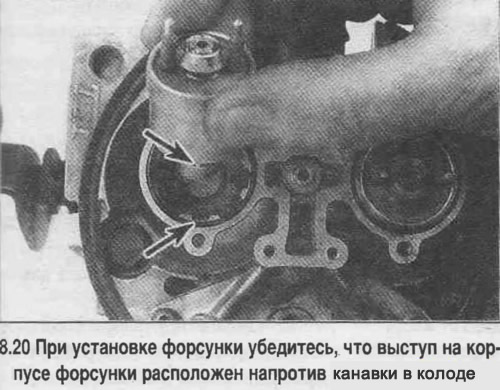
20. Install the nozzle (see photo).


21. Install all removed parts.


Throttle Position Sensor (TPS sensor) and idle air valve (IAC valve)


22. The procedure for replacing these parts of the throttle pipe is discussed in Chapter 6.

Fuel flow meter housing


23. Disconnect the connectors from the injectors.

24. Remove the fuel flow meter/pressure regulator cover, gasket and pressure regulator seal.

25. Remove the injectors.

26. Disconnect the fuel lines, remove the sealing rings.

27. Unscrew the nuts and disconnect the fuel pipes from the fuel flow meter housing (see photo). Pay attention to the location of the nuts, which should be tightened in place. The holes of the intake tube nuts are of a larger diameter.
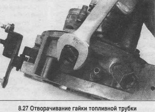
27. Unscrew the nuts and disconnect the fuel pipes from the fuel flow meter housing (see photo).…


28. Remove the gaskets from the nuts.

29. Loosen the screw and remove the flow meter housing (see photo).
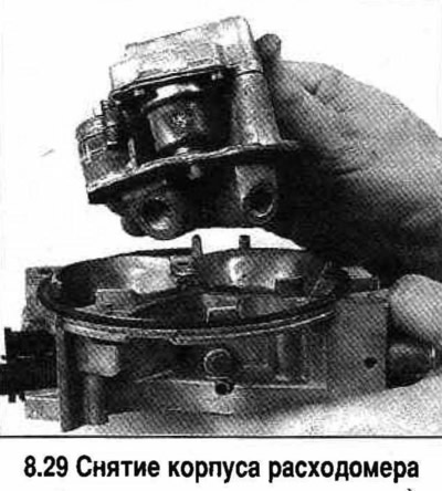
29. Loosen the screw and remove the flow meter housing (see photo).


30. Assembly is performed in reverse order. Replace all seals of the disassembled connections.

The article was checked: Vladimir Romannikov
This article is available at russian, bulgarian, belarusian, ukrainian, serbian, croatian, romanian, polish, slovak, hungarian

Share information:

Previous articles
Tahoe 1: Fuel and exhaust systems
Next articles

Throttle body (TBI module) — removal and installation
Throttle body (TBI system) — general information
Fuel lines and fittings — repair and replacement
Fuel pump — removal and installation
Fuel Pump/Fuel Pressure — Check
Sequential Fuel Injection System — General Information
Fuel injection module (Central SFI system) — removal and installation
Fuel distributor and injectors (SFI) — removal and installation
Fuel pressure regulator — removal and installation
Throttle body — removal and installation


See similar articles on the topic of Chevrolet cars:
Throttle body Chevrolet Aveo T250 (2006-2011)
Electronic throttle body Chevrolet Captiva 1 (2006-2018)
Engine parts defect detection Chevrolet Cruze 1 (2008-2016)
Removal and disassembling the fuel module Chevrolet Lacetti 1 (2002-2009)
Checking the throttle position sensor and its circuits Chevrolet Lanos T150 (2002-2009)
Painting of individual body parts Chevrolet Niva 1 (2002-2016)
Throttle Body — Removal and Installation (3.1L) Chevrolet Lumina 1 (1989-1994)
Link in different formats to this page


Visitor comments

No comments yet


How much will 11 + 35 =


Tahoe 2 and 3 (2000-2014) 
  • General information
  • Vehicle characteristics
  • Vehicle device
  • Manual
  • Maintenance
  • Power unit
  • Engine repair
  • Engine overhaul
  • Cooling system
  • Injection and control system
  • Exhaust system
  • Engine electrical equipment
  • Transmission
  • Automatic gearbox 4L60, 4L65, 4L70
  • Automatic gearbox 6L50, 6L80, 6L90
  • Transfer case
  • Drive shafts and cardan
  • Front drive axle
  • Rear drive axle
  • Chassis
  • Car suspension
  • Steering
  • Brake system
  • Body (until 2007)
  • Exterior (external elements)
  • Interior (internal elements)
  • Doors, locks and windows
  • Heating and air conditioning
  • Security System (SRS)
  • Body (since 2007)
  • Exterior (external elements)
  • Doors, locks and windows
  • Interior (internal elements)
  • Electrical equipment
  • Electrical appliances (until 2007)
  • Lighting and lamps (until 2007)
  • Audio system (until 2007)
  • Electrical appliances (since 2007)
  • Lighting and lamps (since 2007)
  • Audio system (since 2007)
  • Wiring diagrams (2000-2005)
  • Wiring diagrams (2005-2007)
  • Wiring diagrams (since 2007)


Tahoe 1 (1992-2000) 
  • General information
  • User manual
  • Maintenance
  • Power unit
  • Engine in a car
  • Engine removed
  • Cooling system
  • Heating and air conditioning
  • Fuel and exhaust systems
  • Decreased toxicity
  • Transmission
  • Manual gearbox
  • Automatic gearbox
  • Transfer case
  • Clutch and drive shafts
  • Chassis
  • Brake system
  • Car suspension
  • Steering
  • Body
  • Repair of body elements
  • Electrical equipment
  • Engine electrics
  • Equipment and devices
  • Electrical circuits


ChevyMan.ru © 2017-2026 · Mobile version · Feedback · Site search · Interesting to read · Sitemap: EN BG BY UA RS HR RO PL SK HU

Aveo 2003-2008 · Aveo 2006-2011 · Aveo 2012-2018 · Captiva 2006-2018 · Cruze 2008-2016 · Lacetti 2002-2009 · Lanos 2002-2009 · Niva 2002-2016 · Tahoe 1992-2000 · Tahoe 2000-2014 · Lumina 1 1989-1994 · Trailblazer 1 2001-2008 · Orlando 1 2010-2018 ·
🛡️ For your security and to improve our service, this site uses cookies. You can disable them in your browser.