
Early models
Note: The intake manifold, throttle body, fuel rail and injectors can be removed and installed as a single unit.
1. If necessary, remove the throttle body, see items 41-43 for later models.
2. If necessary, remove the fuel injectors, see items 44-46 for later models.
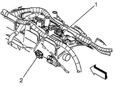
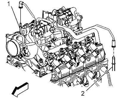
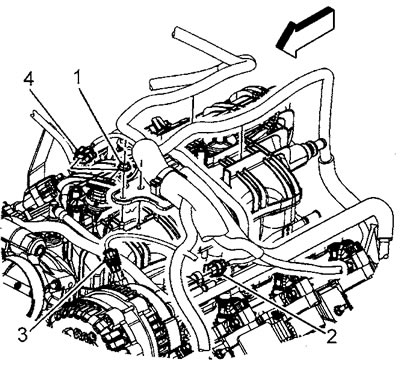
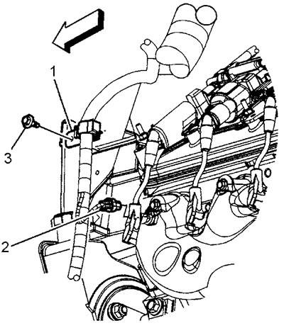
3. Disconnect the connectors of the absolute air pressure sensor (1) and the knock sensor (2).
4. Remove the knock sensor wire harness connector from the intake manifold.
5. Place the bundle of wires to the side.
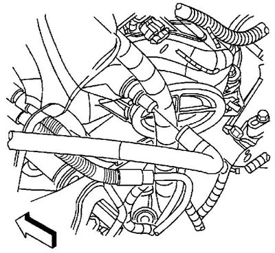
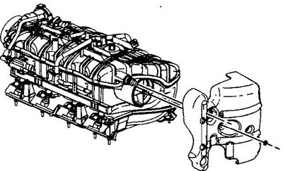
6. If the vehicle is equipped with a brake booster, disconnect the booster hose from the fitting at the rear of the intake manifold.
7. Remove the crankcase ventilation hose.
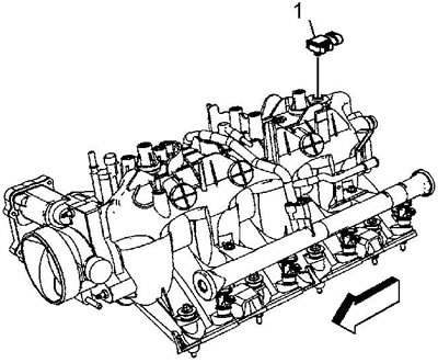
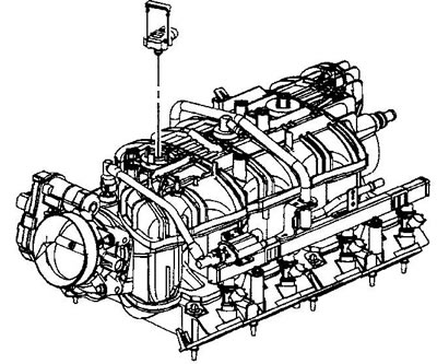
8. Remove the absolute air pressure sensor (1) from the intake manifold.
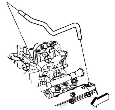
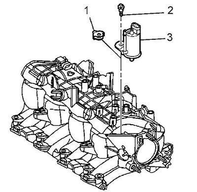
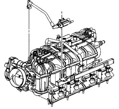
9. Remove the fuel vapor canister purge valve tube by disconnecting the tube from the valve (1) and the accumulator tube (2).
10. Loosen the bolt (2) securing the cleaning valve (3), remove the valve and seal (1) from the intake manifold.
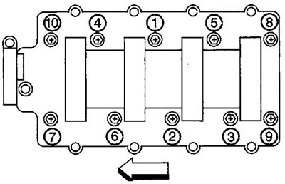
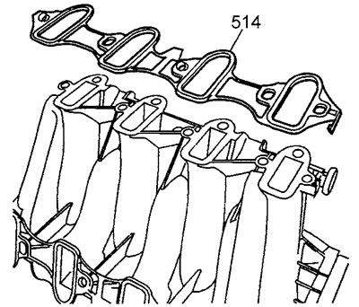
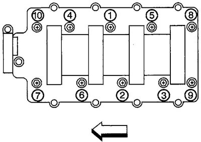
11. Loosen the intake manifold mounting bolts. When installing, apply sealant to the threads of the mounting bolts and tighten the mounting bolts in the order shown in the figure. Tightening torque: 1st pass 5 Nm; 2nd pass 10 Nm.
12. Remove the intake manifold.
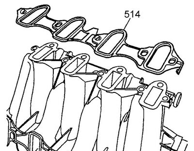
13. Remove the gaskets (514) from the intake manifold and discard the gaskets.
14. Installation is carried out in reverse order.
Late models
1. Remove the air filter outlet duct.
2. Remove the generator.
3. Loosen the nut (1) securing the engine wire harness. Tightening torque 5 Nm.
4. Remove the wire harness holder from the stud.
5. Disconnect the connector (2) of the fuel vapor canister purge valve.
6. Disconnect the connector (4) of the absolute air pressure sensor in the intake manifold.
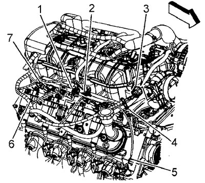
7. Remove the holder (2) of the left half-block wire harness connector.
8. Disconnect the connector (1) of the ignition coil of the left half-block.
9. Disconnect the connector (3) of the fuel injectors of the left half-block.
10. Remove the clips (4) supporting the wire bundle from the studs of the left half-block ignition coil bracket.
Late models, to points 7-10
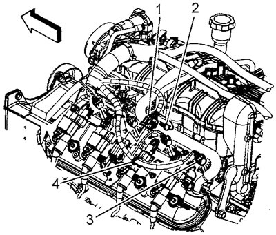
11. Remove the holder (2) of the right half-block wire harness connector.
12. Disconnect the connector (1) of the ignition coil of the right half block.
13. Disconnect the throttle actuator connector (3).
14. Remove the clips (4) supporting the wire harness from the battery charging generator cable.
15. Remove the clips (6) supporting the wire bundle from the studs of the ignition coil bracket of the right half-block.
16. Disconnect the connector (7) of the fuel injectors of the right half-block.
17. Loosen the bolt (3) securing the clip (1) of the engine wire harness. Tightening torque 9 Nm.
18. Disconnect the coolant temperature sensor connector (2).
19. Gather the branches of the wire bundle and tie the wires away from the cowl panel fairing.
20. Remove the brake booster vacuum hose clamp from the booster.
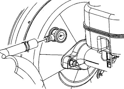
21. Remove the vacuum hose from the booster fitting.
22. Secure the brake booster vacuum hose to the intake manifold.
23. Disconnect the fuel vapor accumulator cleaning tube (1) from the cleaning valve.
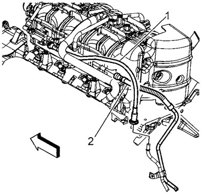
24. Disconnect the quick connector (2) of the fuel supply pipe.
25. Remove the crankcase ventilation hose from the intake manifold fitting.
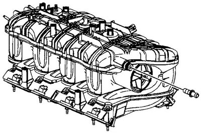
26. Loosen the bolts (512) securing the intake manifold.
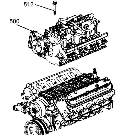
When installing, tighten the mounting bolts in the order shown in the figure. Tightening torque: 1st pass 5 Nm; 2nd pass 10 Nm.
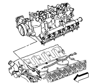
27. Remove the intake manifold (500).
28. Remove and discard the intake manifold gaskets (514).
29. Close the cylinder head intake ports to prevent dirt from entering the engine cylinders.
30. When replacing the intake manifold, follow the steps below.
31. Place the intake manifold on a clean workbench.
32. Remove the brake booster vacuum hose clamp from the intake manifold.
33. Remove the vacuum hose from the intake manifold fitting.
34. Unscrew the nut securing the upper cover of the intake manifold.
35. Remove the upper intake manifold cover.
36. Remove the absolute air pressure sensor holder.
37. Remove the absolute air pressure sensor.
38. Disconnect the fuel vapor recovery system tube from the intake manifold.
39. Disengage the retainer securing the fuel vapor canister purge valve to the fuel manifold.
40. Remove the fuel vapor canister purge tube and valve.
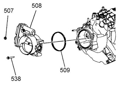
41. Loosen the bolts (538) and nuts (507) securing the throttle body (508). Tightening torque 10 Nm.
42. Remove the throttle body.
43. Remove and discard the throttle body gasket (509).
44. Loosen the fuel manifold mounting bolts. Tightening torque 10 Nm.
Note: Apply locking adhesive to the bolt threads during installation.
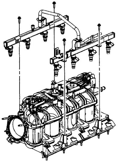
45. Remove the fuel manifold.
Caution: Lift the fuel manifold evenly until all fuel injectors are clear of their sockets.
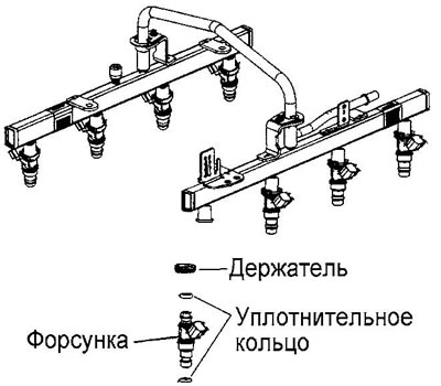
46. Remove and discard the lower fuel injector O-rings.
Note: When installing, lubricate NEW O-rings with engine oil.
47. Remove the brake booster vacuum hose fitting.
Note: When removing the fitting, apply even pressure to the red spacer.
48. Installation is carried out in reverse order.
Intake Manifold Upper Cover
1. Remove the intake manifold.
2. Perform operations according to items 32-35 of the section "Intake manifold. Removal and installation" of this chapter.
(Original version of the article on the website «CHEVYMAN»)