


Stretcher (front axle beam) with longitudinally spaced attachment points to the body (four attachment points: two on the right and two on the left). The suspension arms, rack and pinion steering mechanism, and anti-roll bar of the vehicle are mounted on the subframe;
Transverse levers fixed to the subframe using two rubber-metal hinges (silent blocks), the front of which has a longitudinal horizontal axis, and the rear one has a vertical axis. The other end of the transverse lever is connected by means of a ball joint (ball joint) with a steering knuckle.
Ball joint is secured to the lever by two bolts. The attachment points of the lever to the subframe are spaced longitudinally relative to the vehicle at a sufficient distance to ensure rigidity of the wheel attachment when traction or braking force is applied to it. Therefore, the front suspension does not contain longitudinal reaction rods; - steering knuckles, the lower part of which is connected by means of ball joints to the suspension arms, and the upper part is attached to the shock absorber struts using two bolts each. The front wheel hub bearing is pressed into the steering knuckle. The front wheel hub is pressed into the bearing. The splined shaft of the constant velocity joint (CV joint) of the drive shaft enters the hub.
Splined part of CV joint secured in the hub with a nut screwed onto the threaded end of the splined CV joint shaft. In addition, the steering knuckle is connected to the rack and pinion steering mechanism via a tie rod end. The front disc brake caliper and shield covering the open inner part of the brake disc are also secured to the steering knuckle;
Anti-roll bar the car is a curved elastic rod that works like a torsion bar (for twisting). If there is a difference in the position of the right and left levers, twisting forces arise in the stabilizer torsion bar, which prevent the car from rolling when turning. The stabilizer is fixed across the car on the subframe using two clamps and rubber bushings. The ends of the stabilizer are connected to the stabilizer bars using hinges. The other (upper) end of the stabilizer bar is attached to the shock absorber strut housing at the hinge;
Shock absorber struts are connected at the bottom with two bolts to the steering knuckles. The shock absorber rods are attached with rubber-metal hinges to the mudguards of the front wheel arches. The rubber-metal hinge contains a bearing through which the shock absorber rod passes. The bearing eliminates friction when turning the wheel and prevents the shock absorber rod from rotating in the housing. The hinge on the shock absorber rod is attached with a nut that is screwed onto the rod.
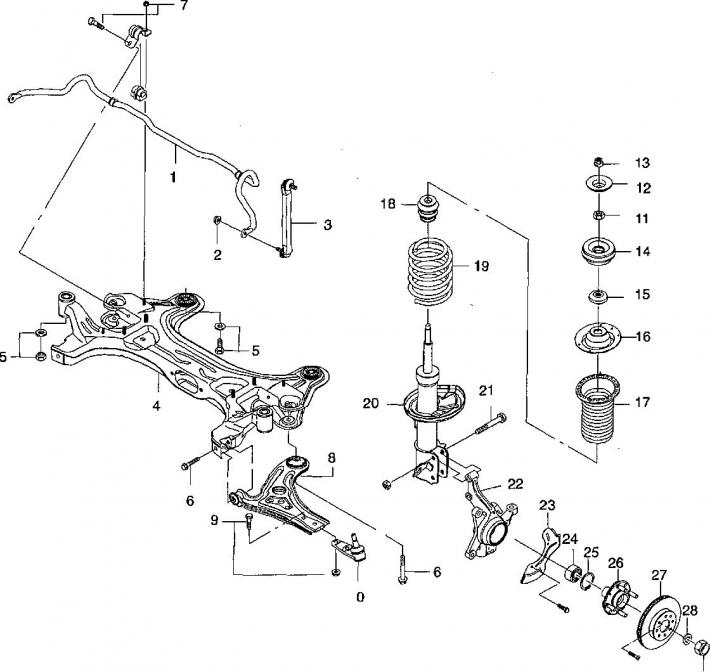
1. Stabilizer; 2. Stabilizer bar mounting nut; 3. Stabilizer bar; 4. Subframe; 5. Subframe mounting nut (front mount); 6. Lever mounting bolt (front silent block); 7. Stabilizer clamp nut; 8. Suspension arm; 9. Bolt for fastening the ball joint to the suspension arm; 10. Ball joint; 11. Shock absorber rod nut; 12. Washer; 13. Upper nut for fastening the rack to the body; 14. Upper cushion of the shock absorber strut; 15. Bearing; 16. Upper spring stop; 17. Upper elastic spring stop with corrugated dust cover; 18. Buffer; 19. Coil spring 20. Lower spring stop; 21. Steering knuckle mounting bolt; 22. Steering knuckle; 23. Brake disc shield; 24. Hub bearing; 25. Retaining ring; 26. Wheel hub 27. Brake disc; 28. Washer; 29. Nut.
The lower stop of the front suspension spring is located on the shock absorber strut housing, and the upper stop of the spring (stamped steel cup) is secured to the rod with a nut. The suspension spring is pre-compressed between the upper and lower stops. Thus, the shock absorber struts contain an elastic element and act as vibration dampers for the suspension. The upper end of the stabilizer bar is secured to the shock absorber strut housing with a hinge.
Tightening torques for front suspension threaded connections
| Ball joint to lever nuts | 50 Nm |
| Ball joint nut with steering knuckle | 100 Nm |
| Front silent block bolt | 110 Nm |
| Front balance arm mounting bolts | 110 Nm |
| Drive shaft to hub connection nut (final tightening torque) | 300 Nm |
| Shock absorber rod nut | 60 Nm |
| Bolt of the clamp fastening the stabilizer to the subframe | 50 Nm |
| Shock absorber strut to body mounting nuts | 60 Nm |
| Threaded cover for mounting the shock absorber in the strut housing | 200 Nm |
(The article is reprinted from the website ChevyMan.ru)