


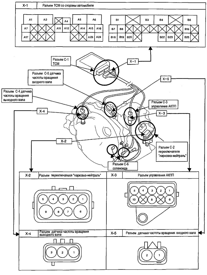
| X-1 | TCM connector from the vehicle side |
| A1 | "Weight" |
| A2 | "Mass" of the electromagnetic pressure control valve |
| A4 | Pressure control solenoid valve |
| A5 | Electromagnetic locking valve |
| A6 | "+" Ignition |
| A7 | Data bus (isolated "-") |
| A11 | Working fluid temperature sensor |
| A12 | "Mass" of the working fluid temperature sensor |
| A14 | Solenoid valve synchronization |
| A15 | 2nd gear shift solenoid valve |
| A16 | 1st gear shift solenoid valve |
| A17 | "+" Data bus |
| A23 | "Weight" |
| A24 | B+ |
| B1 | Position signal R |
| VZ | Watch |
| B4 | Retention |
| B6 | Yes |
| B7 | Position signal D |
| B8 | Position signal N |
| B16 | input shaft speed sensor "Ground" |
| B18 | Position signal L |
| B19 | Position signal 2 |
| B20 | Position signal P |
| B22 | Brake light switch |
| B23 | DLC |
| B25 | Output shaft speed sensor |
| X-2 | "Parking-neutral" switch connector |
| 1 | Position signal P |
| 2 | Position signal R |
| 3 | "Weight" |
| 4 | Position signal 2 |
| 5 | Position signal N |
| 6 | ST(-) |
| 7 | Position signal D |
| 8 | Position signal 1 |
| 9 | ST(+) |
| X-3 | Automatic transmission control connector |
| 1 | Working fluid temperature sensor |
| 2 | Solenoid valve synchronization |
| 3 | Pressure control solenoid valve |
| 4 | Electromagnetic locking valve |
| 5 | 1st gear shift solenoid valve |
| 6 | "Mass" of the working fluid temperature sensor |
| CO | "Mass" of the electromagnetic pressure control valve |
| 10 | 2nd gear shift solenoid valve |
| X-4 | Output shaft speed sensor connector |
| 1 | Ignition |
| 2 | "Weight" |
| 3 | Output shaft speed sensor |
| X-5 | Input shaft speed sensor connector |
| 1 | input shaft speed sensor "Ground" |
| 2 | Input shaft speed sensor |
Transmission Control Unit (TCU)
Park/Neutral Position Switch (PPS)
The Park/Neutral Position (PNP) switch transmits information from the gear shift lever to the starter and ECU.
The PPN switch can start the engine only in the "P" and "N" positions. (Preventing reckless driving).
The PPN switch makes the reverse light come on when reversing.
It is used for the PPN switch when switching the regulator. The PPN switch transmits information through the combination of the starter circuit and the reversing circuit to the car directly without the TBC.
Synchronizing solenoid
The timing solenoid is mounted directly on the valve body. The solenoid is switched on/OFF (ON/ OFF) by means of a control signal from the control unit. The timing change solenoid inside the valve body activates hydraulic control by turning the forward clutch on and off.
Pressure control solenoid (PCS)
The pressure control solenoid (PCS) is located in the valve body and regulates the transmission fluid pressure system. It is internally grounded in the TCS and operates when battery voltage is applied from the TCS, through the PCS and back to the TCS.
The battery voltage is controlled by alternating current from the BUT.
The current strength shows the position of the throttle.
Transmission Fluid Temperature Sensor (TDK)
The TDK sensor provides the TCU with information about the transmission fluid temperature.
The TCU uses the TTC sensor information to calculate gear shift points and to activate the torque converter lock-up function.
Input shaft speed sensor (ISS)
The SVV sensor is located in the upper part of the gearbox and records the speed of the input shaft of the automatic transmission, based on the number of revolutions of the direct clutch drum.
They transmit the BUT signal.
Output shaft speed sensor (SvyhV)
The SvyazB sensor is located in the upper part of the gearbox and records the vehicle speed based on the number of revolutions of the differential gear.
|
Component |
Function |
|
|
C1 |
Forward clutch |
Connects the input shaft and the front sun gear |
|
C2 |
Straight coupling |
Connects the input shaft and the planetary gear carrier |
|
SZ |
Reverse clutch |
Connects the input shaft and the rear sun gear |
|
B1 |
Leading brake and 2nd brake |
Prevents the rear planetary sun from rotating gear wheel clockwise or counterclockwise |
|
B2 |
2nd brake |
Prevents the outer race of F1 from turning clockwise or counterclockwise, thus preventing rotation rear sun gear counterclockwise |
|
VZ |
1st and reversible brake |
Prevents the planetary gear carrier from rotating clockwise or counterclockwise |
|
F1 |
One-way clutch No.1 |
When B2 is in operation, this clutch prevents the rear from rotating sun gear counterclockwise |
|
F2 |
One-way clutch No.2 |
Prevents the planetary gear carrier from rotating counterclockwise clockwise |
|
Planetary gear wheel |
These gears change the route along which power is transmitted driving force in accordance with the functioning of each clutches and brakes to increase or decrease input and output shaft speed |
|
Gear shift control
If the ATF is below the specification (15°C), shifting to 4th gear is prevented.
Hydraulic control system of automatic transmission
Based on the hydraulic pressure generated by the oil pump, the TCU sends signals to the solenoid, and the hydraulic control system adjusts the hydraulic pressure acting on the torque converter, planetary gear, clutches and brakes according to the vehicle operating conditions.
(Information taken from the official website CHEVYMAN)