
Contents: Cylinder block disassembly procedure ↧ Preparatory work ↧ Notes on removing the crankshaft ↧ Notes on removing main bearing caps ↧ Notes on disassembling the… ↧ Checking the degree of wear of… ↧ Assembly ↧ Tightening torques ↧ Notes on installing piston rings ↧
Disassemble in the order shown in Figure T250 3.065.
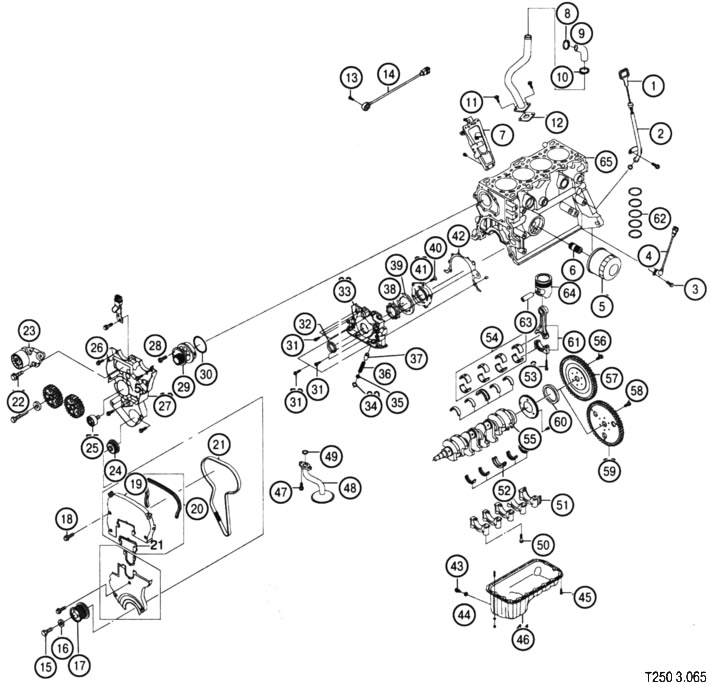
Cylinder block disassembly procedure
- 1. Oil dipstick
- 2. Oil dipstick tube
- 3. Crankshaft position sensor mounting screw
- 4. Crankshaft position sensor
- 5. Oil filter
- 6. Oil filter connector
- 7. Intake manifold support bracket 8 Clamp
- 9. Crankcase ventilation system pipe
- 10. Clamp
- 11. Screw
- 12. Gasket
- 13. Knock sensor mounting screw
- 14. Knock sensor
- 15. Crankshaft pulley mounting screw
- 16. Washer
- 17. Crankshaft pulley
- 18. Cover fastening screw
- 19. Upper front timing belt cover
- 20. Upper front timing belt cover gasket
- 21. Timing belt
- 22. Timing belt tensioner fastening screw
- 23. Timing belt tensioner
- 24. Timing drive drive toothed pulley
- 25. Idle pulley
- 26. Timing belt drive rear cover fastening screw
- 27. Rear timing belt cover
- 28. Coolant pump mounting screw
- 29. Coolant pump
- 30. Coolant pump gasket
- 31. Oil pump mounting screws
- 32. Oil pump seal
- 33. Front cover of oil pump
- 34. Screw for fastening the pressure reducing valve
- 35. Seal
- 36. Pressure reducing valve spring
- 37. Pressure reducing valve piston
- 38. Oil pump gear
- 39. Oil pump gear
- 40. Oil pump rear cover mounting screw
- 41. Oil pump rear cover
- 42. Oil pump gasket
- 43. Screw
- 44. Threaded ring
- 45. Oil pan mounting screw
- 46. Oil pan
- 47. Screw
- 48. Oil scraper tube
- 49. Gasket
- 50. Main bearing cap fastening screw
- 51. Main bearing cap
- 52. Main bearing shell kit
- 53. Connecting rod bearing cap fastening screw
- 54. Connecting rod bearing shells
- 55. Crankshaft
- 56. Flywheel mounting screw (manual transmission)
- 57. Flywheel (manual transmission)
- 58. Flywheel mounting screw (automatic transmission)
- 59. Flywheel (automatic transmission)
- 60. Crankshaft sealing ring
- 61. Connecting rod
- 62. Piston rings
- 63. Piston pin
- 64. Piston
- 65. Cylinder block
Preparatory work
- remove cylinder head;
- remove timing drive components;
- remove the oil pan, oil filter and oil pump.
Notes on removing the crankshaft
Before removing the main bearing caps, the connecting rods must be disconnected from the crankshaft and the pistons must be pushed out through the top of the cylinder block.
Notes on removing main bearing caps
When removing the main bearing caps, mark their locations. When reassembling, they must be installed in their original locations.
Notes on disassembling the connecting rod and piston group
When disassembling the connecting rod and piston group, mark the locations of the connecting rods and connecting rod bearing caps. When reassembling, they must be installed in their original locations.
Checking the degree of wear of cylinder block elements
Checking the crankshaft
Control parameters:
- main journal diameter: 55 mm;
- crank pin diameter: 43 mm;
- maximum taper of main journal: 0.005 mm;
- maximum taper of the crank journal: 0.005 mm;
- maximum deviation from the circular shape of the main journal: 0.004 mm;
- maximum deviation from the round shape of the crank pin: 0.004 mm;
- main bearing clearance: 0.026-0.042 mm;
- connecting rod bearing clearance: 0.019-0.070 mm;
- crankshaft end runout: 0.1 mm;
- connecting rod side clearance: 0.070-0.242 mm.
Checking the piston pins
Control parameters:
- finger diameter: 18 mm;
- finger offset: 0.5-0.7 mm.
Checking piston rings
Control parameters:
- gap in the joint of the upper compression ring: 0.15-0.3 mm;
- gap in the joint of the 2nd compression ring: 0.3-0.5 mm;
- axial clearance in the groove of the upper compression ring: 0.05-0.09 mm;
- axial clearance in the groove of the 2nd compression ring: 0.05-0.09 mm.
Checking the pistons
Control parameters:
- piston diameter: 78.97 mm
- clearance between piston and cylinder wall: 0.03 mm.
Checking the cylinders
Control parameters:
- cylinder diameter: 79.0 mm
- maximum deviation from roundness: 0.0065 mm;
- maximum taper: 0.07 mm.
Assembly
Assembly is carried out in the reverse order of disassembly.
Tightening torques
| Element of the system | Tightening torque |
| Main bearing cap mounting screw | 50 Nm + 45° |
| Connecting rod bearing cap fastening screw | 25Nm + 30° + 15° |
| Oil pump mounting screw | 10 Nm |
| Oil pump inlet pipe mounting screw | 10 Nm |
| Oil pan mounting screw | 10 Nm |
| Rear timing belt cover mounting screw | 10 Nm |
Notes on installing piston rings
When installing, distribute the piston ring gaps as shown in the figure.
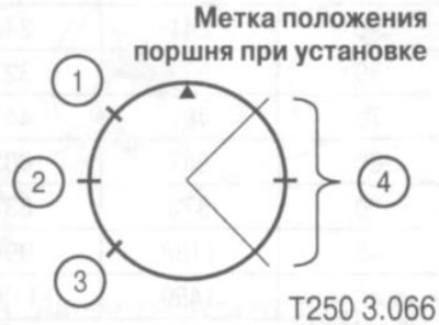
1. Joint of the radial expander of the composite oil scraper ring.
2. Second compression ring gap.
3. Joint of the axial expander of the composite oil scraper ring.
4. Clearances of the first compression ring and the rings of the composite oil scraper ring.
[The original article can be found on the resource: ChevyMan.ru]