Contents: Preparatory work ↧ Notes on removing the intake and… ↧ Notes on cylinder head removal ↧ Notes on removing camshaft bearing… ↧
Disassemble in the order shown in the figure.
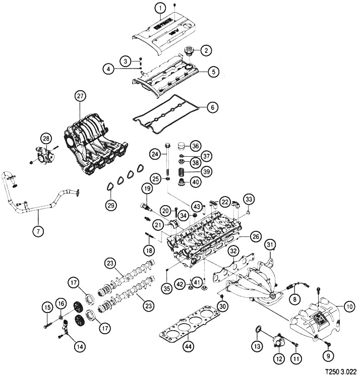
- 1. Decorative engine cover
- 2. Filler cap
- 3. Cylinder head cover bolts
- 4 Cylinder head mounting screw washer
- 5. Valve cover
- 6. Cylinder head cover gasket
- 7. Exhaust gas recirculation pipe
- 8. Oxygen sensor
- 9. Heat shield mounting screw
- 10. Heat shield
- 11. Thermostat mounting screw
- 12. Thermostat
- 13. Thermostat seal
- 14. Camshaft position sensor
- 15. Camshaft sprocket mounting screw
- 16. Washer
- 17. Camshaft sealing ring
- 18. Pin
- 19. Coolant temperature sensor
- 20. Camshaft bearing front cover fastening screw
- 21. Front camshaft bearing cover
- 22. Camshaft bearing cap
- 23. Camshaft
- 24. Cylinder head mounting screw
- 25. Washer
- 26. Cylinder head
- 27. Intake manifold assembly
- 28. Throttle control mechanism
- 29. Intake manifold gaskets
- 30. Exhaust manifold mounting nut
- 31. Exhaust manifold
- 32. Exhaust manifold gasket
- 33. Plug
- 34. Plug
- 35. Plug
- 36. Hydraulic valve clearance compensator
- 37. Valve retaining crackers
- 38. Upper valve spring stop
- 39. Valve spring
- 40. Valve stem seal with lower spring stop
- 41. Exhaust valve
- 42. Inlet valve
- 43. Valve guide bushing
- 44. Cylinder head gasket
Preparatory work
Before removing and disassembling the cylinder head, the following work must be performed:
- disconnect the negative battery cable;
- unscrew the mounting screws and remove the decorative engine cover;
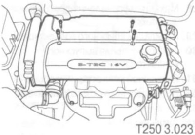
- disconnect the breather from the cylinder head cover;
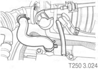
- disconnect the crankcase ventilation pipe from the cylinder head cover;
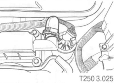
- disconnect the camshaft position sensor (CMP) connector;
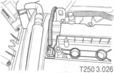
- disconnect the vacuum hoses;
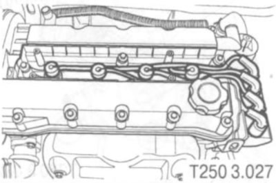
- disconnect the spark plug wires from the spark plugs (see figure T250 3.027);
- unscrew the mounting screws and remove the cylinder head cover;
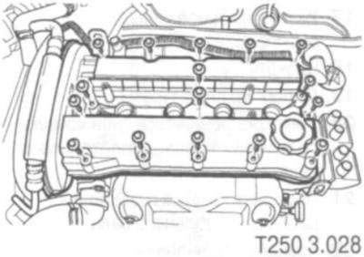
- remove the cylinder head cover gasket;
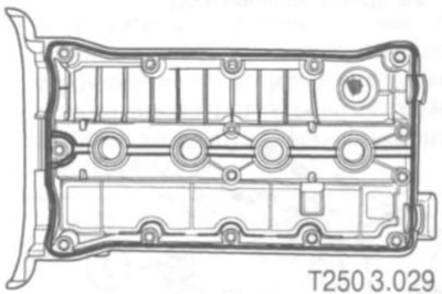
- perform an operation to reduce the pressure in the fuel system. To do this, let the engine run for 10 seconds with the fuel pump disconnected. To disconnect the fuel pump, remove the fuse;
- drain coolant;
- disconnect the breather from the cylinder head cover;
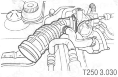
- disconnect the intake air temperature (IAT) sensor connector;
- disconnect the air supply pipe from the throttle body;
- unscrew the mounting screws and remove the air filter;
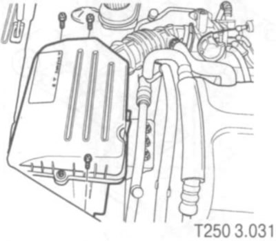
- disconnect the air conditioning pressure sensor (ACP) connector;
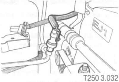
- disconnect the Idle Air Control (IAC) valve connector;
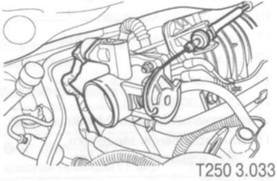
- disconnect the throttle position sensor (TPS) connector;
- disconnect the cable from the throttle valve and from the intake manifold;
- disconnect the engine coolant inlet/outlet hose from the throttle body;
- disconnect the manifold pressure (MAP) sensor;
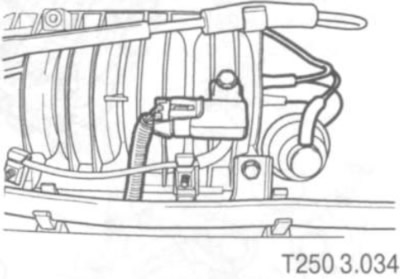
- disconnect the brake booster vacuum hose;
- disconnect the variable geometry induction solenoid (VGIS) connector;
- disconnect the variable geometry induction solenoid (VGIS) vacuum reservoir hose;
- disconnect the camshaft position sensor (CMP) connector;
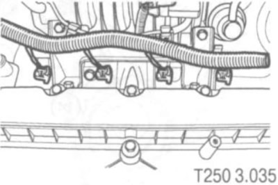
- disconnect the fuel injector harness connectors;
- disconnect the fuel line;
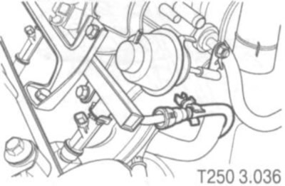
- unscrew the nut and remove the power steering pressure hose mounting bracket;
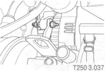
- remove the power steering pressure hose;
- remove the generator adjusting nut;
- disconnect the exhaust gas recirculation (EGR)valve connector;
- disconnect the electronic ignition system coil connector;
- disconnect the front heated oxygen sensor connector;
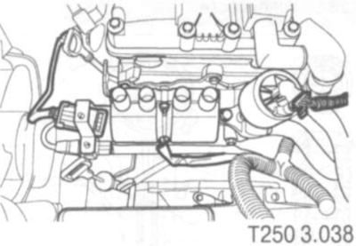
- disconnect the front heated oxygen sensor connector;
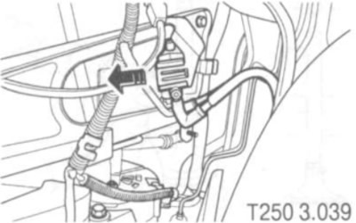
- remove the right front wheel;
- unscrew the bolts and remove the lower engine protection;
- remove the purge solenoid valve from the intake manifold support bracket;
- unscrew the upper and lower screws securing the intake manifold support bracket and remove it;
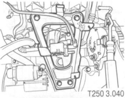
- disconnect the coolant temperature sensor (ECT) connector;
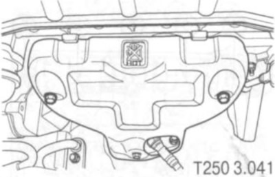
- unscrew the screws and remove the exhaust manifold heat shield;
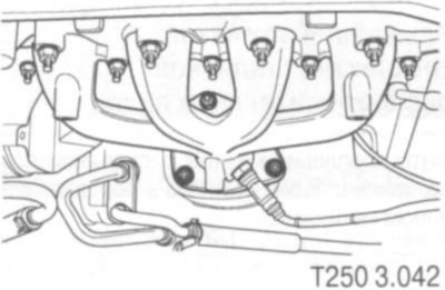
- unscrew the nuts securing the catalytic converter from the exhaust manifold;
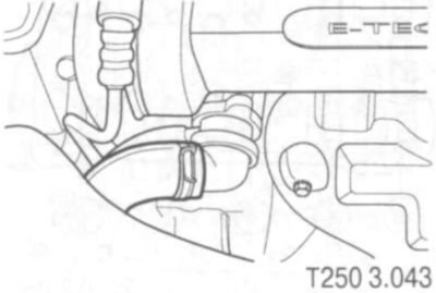
- remove the radiator hose from the thermostat;
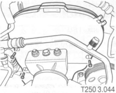
- unscrew the mounting screws and remove the upper front timing belt cover (see figure T250 3.044);
- unscrew the mounting screw and remove the crankshaft pulley;
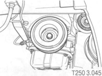
- unscrew the mounting screws and remove the lower front timing belt cover;
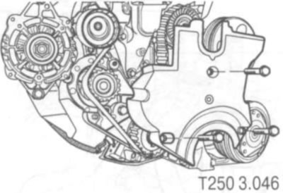
- remove timing belt;
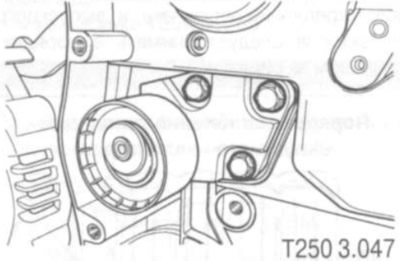
- unscrew the mounting screws and remove the automatic timing belt tensioner;
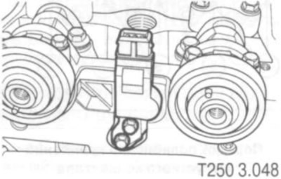
- unscrew the mounting screws and remove the camshaft position sensor (CMP);
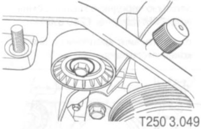
- unscrew the fastening screws and remove the idler pulley of the timing belt drive (see figure T250 3.049);
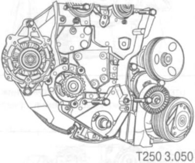
- unscrew the mounting screws and remove the rear timing belt cover (see fig T250 3.050);
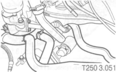
- disconnect the heater outlet hose from the coolant pipe (see figure T250 3.051).
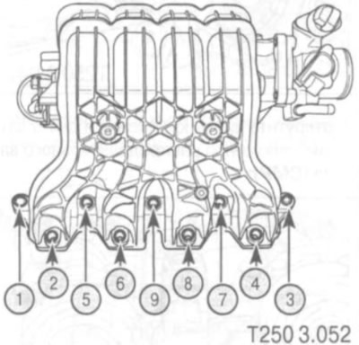
Notes on removing the intake and exhaust manifolds
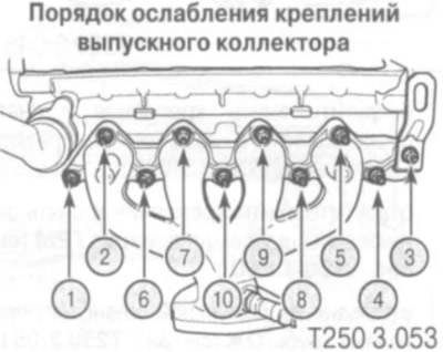
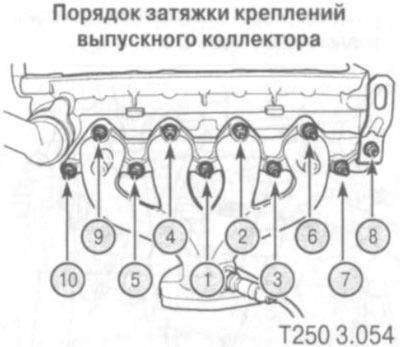
The intake and exhaust manifold mounting nuts should be removed in the order shown in the figure.
Notes on cylinder head removal
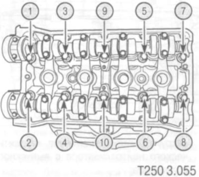
The cylinder head should be removed together with the intake and exhaust manifolds. The cylinder head mounting screws should be removed in the order shown in the figure.
Notes on removing camshaft bearing caps
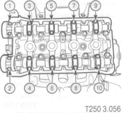
The camshaft cover mounting screws should be removed in the order shown in the figure.