
ChevyMan.ru
Mazda Mitsubishi Toyota Land Rover Honda Kia Nissan
English Русский
Български
Беларускі
Український
Српски
Hrvatski
Română
Polski
Slovenský
Magyar
|
Articles | Sitemap | Contacts |


Home   Aveo   Captiva   Cruze   Lacetti   Lanos   Niva   Tahoe   Others  
Aveo T300 (2012-2018) Aveo T250 (2006-2011) Aveo T200 (2003-2008)
  • Home
  • Aveo
  • T300 (2012-2018)
  • Transmission
  • Clutch
  • Removal and installation the clutch

Removal and installation the clutch (Chevrolet Aveo T300)

            0

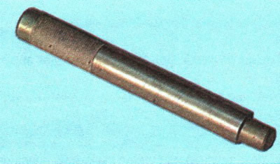
You will need: a key "11" (a socket head is more convenient), mounting blade...

You will need: a key «11» (a socket head is more convenient), mounting blade...


...mandrel for centering the driven disk (can be made from the primary shaft of the gearbox by removing the gears).
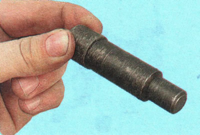
...mandrel for centering the driven disk (can be made from the primary shaft of the gearbox by…


You can use a commercially available mandrel for front-wheel drive VAZ vehicles.

The main faults that require removal and disassembly of the clutch to eliminate:
  • elevated (compared to usual) noise when engaging the clutch;
  • jerks when operating the clutch;
  • incomplete clutch engagement (the clutch is slipping);
  • incomplete disengagement of the clutch (the clutch "leads").

USEFUL TIP: If the clutch fails, we recommend replacing all of its components at the same time (driven and pressure plates, clutch release bearing): the work of replacing the clutch is labor-intensive, and the service life of undamaged clutch elements has already been reduced, and if they are reinstalled, then the clutch may need to be replaced again after a relatively short mileage.


1. Remove the gearbox see. "Removal and installation of a manual gearbox").
1. Remove the gearbox see. «Removal and installation of a manual gearbox»).


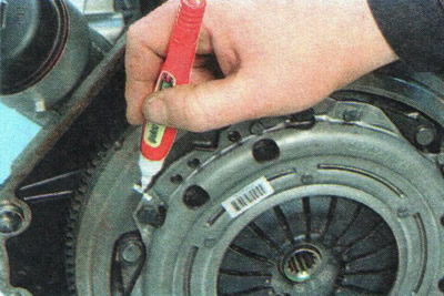
2. If you are going to install the old pressure plate, mark it in any way (for example, with paint) the relative position of the disc casing and the flywheel to set the pressure plate to its previous position (to maintain balance).

NOTE: For clarity, some of the following operations are shown with the engine removed.

NOTE: For clarity, some of the following operations are shown with the engine removed.


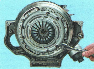
3. Hold the flywheel with a mounting blade (or a large screwdriver) from turning, unscrew the six bolts securing the clutch pressure plate housing to the flywheel. Loosen the bolts evenly: each bolt two turns of the wrench, moving from bolt to bolt by diameter.
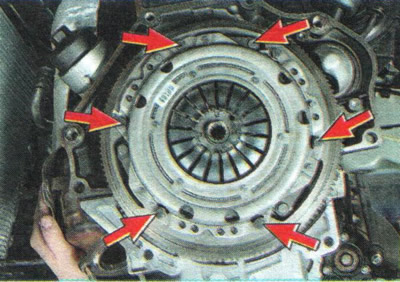
3. Hold the flywheel with a mounting blade (or a large screwdriver) from turning, unscrew the six…


NOTE: This is the location of the clutch housing bolts that secure the engine flywheel to the clutch housing.


NOTE: This is the location of the clutch housing bolts that secure the engine flywheel to the…


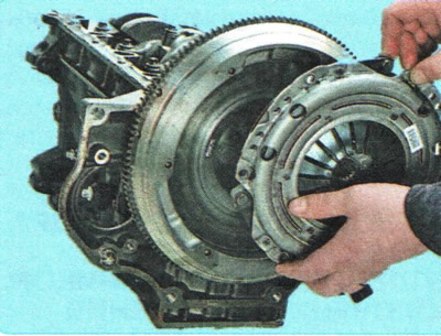
4. Remove the pressure and driven clutch discs from the flywheel, holding the driven disc.
4. Remove the pressure and driven clutch discs from the flywheel, holding the driven disc.


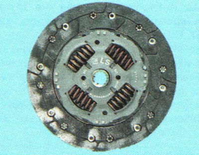
5. Inspect the driven clutch disc. Cracks on the driven disc parts are not allowed.
5. Inspect the driven clutch disc. Cracks on the driven disc parts are not allowed.


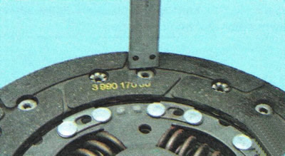
6. Check the degree of wear of the friction linings. If the rivet heads are recessed less than 0.3 mm, the surface of the friction linings is oily or the riveted connections are loose, the driven disk must be replaced.


NOTE: If the driven disk linings are oily, check the condition of the transmission input shaft seal. It may need to be replaced.

NOTE: If the driven disk linings are oily, check the condition of the transmission input shaft…


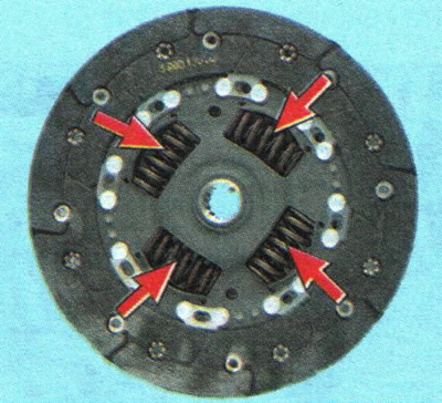
7. Check the reliability of the damper springs in the sockets of the driven disk hub by trying to move them in the sockets of the hub by hand. If the springs move easily in the sockets or are broken, replace the disk.

8. Check the runout of the driven disk if its warping is detected during visual inspection. If the runout is more than 0.5 mm, replace the disk.
8. Check the runout of the driven disk if its warping is detected during visual inspection. If the…


9. Inspect the flywheel friction working surfaces...
9. Inspect the flywheel friction working surfaces...


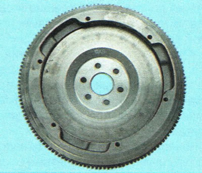
10. ...and the pressure plate, paying attention to the absence of deep scratches, nicks, dents, obvious signs of wear and overheating. Replace defective units.


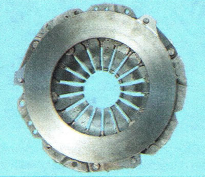
11. If the riveted connections of the casing parts and the pressure plate become loose, replace the pressure plate assembly.
11. If the riveted connections of the casing parts and the pressure plate become loose, replace the…


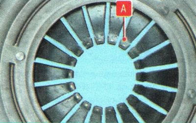
12. Assess the condition of the diaphragm spring of the pressure plate by visual inspection. The presence of cracks on the diaphragm spring is not allowed. The contact points of the spring petals with the clutch release bearing must be in the same plane and be without obvious signs of wear (wear should not exceed 0.8 mm). Otherwise, replace the pressure plate assembly.
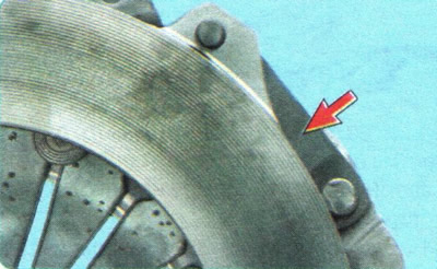
12. Assess the condition of the diaphragm spring of the pressure plate by visual inspection. The…


13. Inspect the connecting links of the housing and the disc. If the links are deformed or broken, replace the pressure plate assembly.

14. Assess the condition of the pressure spring support rings on the outer and inner sides of the spring by visual inspection. The rings should not have cracks or signs of wear. Otherwise, replace the pressure plate assembly.


15. Before installing the clutch, check the ease of movement of the driven disk along the splines of the primary shaft of the gearbox. If necessary, eliminate the causes of jamming or replace defective parts.

16. Apply high-melting grease to the splines of the driven disk hub.
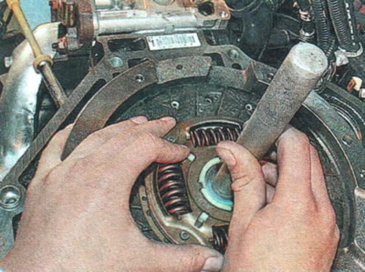
16. Apply high-melting grease to the splines of the driven disk hub.


17. When installing the clutch, first install the driven disk using a mandrel...
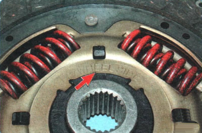
17. When installing the clutch, first install the driven disk using a mandrel...


NOTE: Install the driven disk so that the inscription "FLYWHEEL SIDE" was directed towards the flywheel (the protruding part of the disc hub must be directed towards the diaphragm spring of the clutch housing).
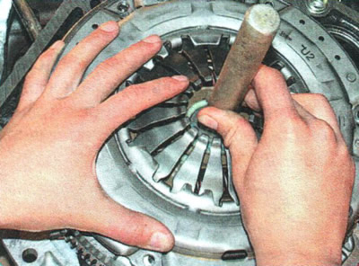

NOTE: Install the driven disk so that the inscription «FLYWHEEL SIDE» was directed towards the…


18. ...and then the pressure plate casing, aligning the marks made before removal, and screw in the bolts securing its casing to the flywheel.

19. Tighten the bolts evenly with a torque of 15 Nm, one turn of the wrench each, moving from bolt to bolt in turn according to diameter.

20. Remove the mandrel and install the gearbox (see "Removal and installation of a manual gearbox").

21. Check the operation of the clutch (see "Checking the Clutch Release Pedal Travel").

The article was checked: Vladimir Romannikov
This article is available at russian, bulgarian, belarusian, ukrainian, serbian, croatian, romanian, polish, slovak, hungarian

Share information:

Previous articles
Aveo T300: Clutch
Next articles

Replacing the working fluid in the clutch release hydraulic drive
Bleeding the clutch release hydraulic drive
Checking the Clutch Release Pedal Travel
Possible clutch malfunctions, their causes and solutions
Clutch design features
Replacing the clutch release drive slave cylinder with the clutch release bearing
Replacing the clutch release master cylinder
Replacing the clutch release hydraulic line
Removal and installation the clutch pedal


See similar articles on the topic of Chevrolet cars:
Brake fluid and clutch fluid Chevrolet Captiva 1 (2006-2018)
Clutch design features Chevrolet Cruze 1 (2008-2016)
Checking the fluid level in the brake and clutch hydraulic reservoir Chevrolet Lacetti 1 (2002-2009)
Replacing fluid in hydraulic brake and clutch drives Chevrolet Lanos T150 (2002-2009)
Clutch release hydraulic drive Chevrolet Niva 1 (2002-2016)
Checking the clutch hydraulic drive Chevrolet Tahoe 1 (1992-2000)
Transmission torque converter clutch Chevrolet Lumina 1 (1989-1994)
Link in different formats to this page


Visitor comments

No comments yet


How much will 16 + 40 =


Aveo T300 (2012-2018) 
  • General information
  • Vehicle device
  • User manual
  • Main malfunctions
  • Maintenance
  • Power unit
  • Engine
  • Lubrication system
  • Cooling system
  • Supply system
  • Exhaust system
  • Transmission
  • Clutch
  • Manual gearbox
  • Automatic gearbox
  • Front wheel drives
  • Chassis
  • Front suspension
  • Rear suspension
  • Steering
  • Brake system
  • Body
  • Exterior
  • Interior
  • Doors and trunk
  • Security systems
  • Electrical equipment
  • Engine electrics
  • Equipment and devices
  • Heating and air conditioning
  • Electrical circuits


Aveo T250 (2006-2011) 
  • Manual
  • Driver's workplace
  • Salon equipment
  • Vehicle characteristics
  • Maintenance
  • Engine 1.5 SOHC
  • Engine repair
  • Fuel supply system
  • Control system
  • Cooling system
  • Engine 1.6 DOHC
  • Engine repair
  • Control system
  • Transmission
  • Clutch
  • Manual gearbox
  • Automatic gearbox
  • Wheel drive
  • Chassis
  • Wheel suspension
  • Steering
  • Brake system
  • Body
  • Exterior
  • Interior


Aveo T200 (2003-2008) 
  • General information
  • User manual
  • Power unit
  • Engine repair 1.5L SOHC
  • Fuel system
  • Control system
  • Cooling system
  • Transmission
  • Clutch
  • Manual gearbox
  • Automatic gearbox
  • Drive shafts
  • Chassis
  • Front suspension
  • Rear suspension
  • Steering
  • Brake system
  • Body
  • Exterior (external elements)
  • Interior (internal elements)
  • Electrical equipment
  • Equipment and devices
  • Electrical circuits


ChevyMan.ru © 2017-2026 · Mobile version · Feedback · Site search · Interesting to read · Sitemap: EN BG BY UA RS HR RO PL SK HU

Aveo 2003-2008 · Aveo 2006-2011 · Aveo 2012-2018 · Captiva 2006-2018 · Cruze 2008-2016 · Lacetti 2002-2009 · Lanos 2002-2009 · Niva 2002-2016 · Tahoe 1992-2000 · Tahoe 2000-2014 · Lumina 1 1989-1994 · Trailblazer 1 2001-2008 · Orlando 1 2010-2018 ·
🛡️ For your security and to improve our service, this site uses cookies. You can disable them in your browser.