


Rear wheel drive models
1. Raise the front of the car and place it on stands. Remove the wheel.
2. Remove the suspension spring.
3. Disconnect the lower ball joint.
4. Take the lever to a car service center to replace the ball joint and bushings.
5. Installation is performed in the reverse order. Install the bolts of the lever axis at the front, finally tighten the bolts after removing the car from the stands. Tighten all nuts to the specified torques. Lubricate the new ball joint of the lever.
All-wheel drive models
6. Raise the front of the car and place it on stands. Remove the wheel.
7. Remove the wheel arch mudguard panel to access the front suspension components.
8. Disconnect the stabilizer bar from the lower arm. -
9. Remove the shock absorber.
10. Disconnect the lateral rod from the main steering rod.
11. Remove the axle shaft.
12. Count the number of threads on the open part of the torsion adjuster bolt, and also mark the relative position of the nut.

13. Loosen the torsion bar adjusting bolt as much as possible without removing the bolt completely. This will reduce the load on the stabilizer bar.
14. Raise the lower control arm with a jack. The jack head should be positioned as close to the control arm ball joint as possible to still provide access to the control arm ball joint pin nut.
15. Disconnect the steering knuckle from the lower control arm ball joint. Remove the steering knuckle and hub assembly, then insert a block of wood between the upper control arm and the frame.
16. Mark the position of the torsion bar relative to the lower arm, then slowly lower the jack until the force from the torsion bar disappears.
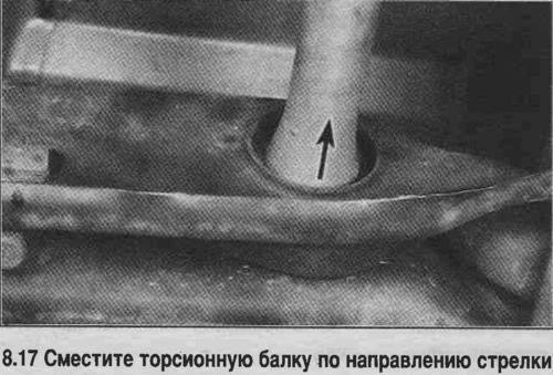
17. Move the torsion beam forward, removing it from the adjusting lever (see photo).
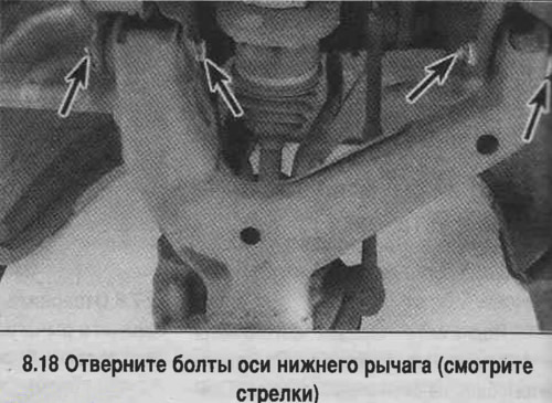
18. Unscrew the bolts and nuts of the lower arm axle, remove the washers (see photo). Remove the lower arm assembly with the torsion beam.
19. Mark the protruding part of the torsion beam with tape to ensure proper installation, then remove the torsion beam from the control arm.
20. Check the condition of the bushings. On some models, the bushings are welded in place and cannot be removed. If the bushings are worn, the arm should be replaced. On some cars, the bushings are removed and installed on a hydraulic press at a car service center.
21. Insert the torsion beam into the hole in the lower arm. Lift the arm assembly with the beam and install it into the hole in the crossmember (if necessary, move the beam in the lever slightly forward). Install the lower control arm into the frame bracket by inserting the front of the arm first.
22. Tighten the control arm axle bolts. They should be inserted so that the bolt heads are facing the front of the car. Install the washers, tighten the nuts, but do not tighten them completely.
23. Move the torsion beam back by inserting it into the adjusting lever.
24. Carefully lift the lower arm with a jack and insert the arm ball joint pin into the steering knuckle eye. Tighten the arm ball joint nut, tighten it to the specified torque and secure with a new cotter pin.
25. Tighten the torsion beam adjusting nut until the distance between the crossmember and the end of the adjusting lever is the same as before removal.
26. Install the axle shaft.
27. Connect the lateral rod to the main steering rod.
28. Install the shock absorber.
29. Attach the stabilizer bar to the lower arm.
30. Install the wheel and lower the vehicle.
31. Tighten the wheel nuts completely.
32. Install the front mudguard panel.
33. Measure the height of the vehicle on each side from the same points on the frame to the ground. If the side on which work was performed is higher or lower than the other side, level the vehicle by turning the torsion beam adjusting bolt. Adjustment is usually achieved in several attempts. When adjusting, roll the vehicle back and forth, load and unload the front of the vehicle to "settle" the suspension components.