


Contents: Upper arm ball joint ↧ Lower arm ball joint ↧ Rear wheel drive models (upper ball… ↧ Rear wheel drive models (lower ball… ↧ Rear wheel drive models (upper or… ↧ All-wheel drive models ↧
Upper arm ball joint
1. Loosen the wheel nuts, lift the front of the car and place it on stands. Set the parking brake. Remove the wheel.
2. Place a floor jack under the lower control arm and lift the arm slightly. Use a large screwdriver to pry up the upper control arm and try to rock it. Any noticeable movement indicates wear of the control arm ball joint. Compress the steering knuckle and try to move it by the top. If you feel any play, replace the control arm ball joint.
Lower arm ball joint
3. Raise the vehicle and place it on stands.
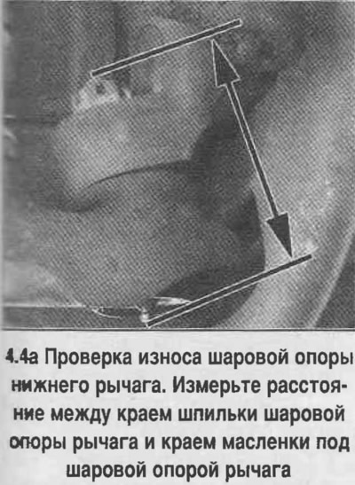
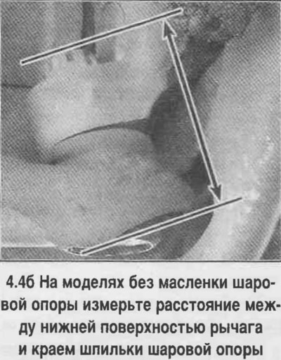
4. Raise the suspension with a jack (the jack must support the weight of the suspension). Measure the distance between the edge of the control arm ball joint stud and the edge of the grease cup under the control arm ball joint (A). If there is no grease cup, measure the distance between the lower surface of the control arm and the upper part of the control arm ball joint (B) (see photo).
5. Remove the jack and repeat the measurement.
6. If the difference between these two dimensions exceeds 2.4 mm (3/32 inch), then the ball joint of the lever is worn out and must be replaced with a new one.
7. Raise the front of the car and place it on stands. Remove the front wheel.
Rear wheel drive models (upper ball joint)
8. Remove the brake caliper, move it to the side and secure it (see Chapter 9).
9. Remove the cotter pin and unscrew the nut from the ball joint of the lever by two turns.
10. Place a jack under the lower arm.
Caution! The jack must remain under the lever during the entire time of removal and installation of the lever ball joint in order to absorb the force from the suspension spring.
11. Press the ball joint of the lever out of the steering knuckle using a puller (see photo).
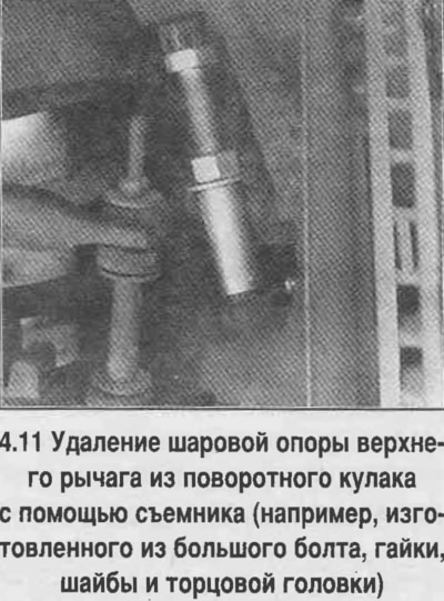
Caution! Do not use a fork-type puller to avoid damaging the rubber boot of the ball joint.
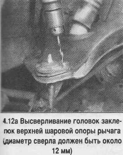
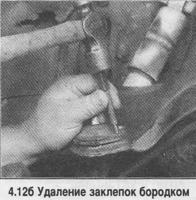
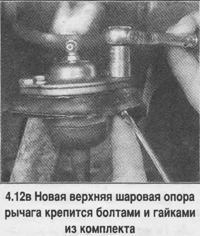
12. To remove the upper ball joint from the control arm, drill out the rivets (see photo). Remove the ball joint and clean the control arm. Install the new upper ball joint in place and secure with the nuts and bolts from the kit (see photo).
Rear wheel drive models (lower ball joint)
13. Remove the lower suspension arm (see below) and take it to a car service center to have a new ball joint pressed out and installed.
Rear wheel drive models (upper or lower ball joints of suspension arms)
14. Clean dirt from the edges of the cone holes in the steering knuckle. Check the condition of the ball joint mounting lugs. If deformations or other damage are found, replace the steering knuckle with a new one (see below).
15. Attach the ball joints of the control arm to the steering knuckle, tighten the nuts to the specified torque.
16. If the cotter pin does not align with the slot in the nut, tighten the nut until the cotter pin can be inserted.
17. Screw in the grease fittings and lubricate the new ball joint.
18. Install the wheels and remove the vehicle from the stands.
19. Check and adjust wheel alignment angles if necessary.
All-wheel drive models
20. Procedure for replacing the upper ball joint of the control arm on all-wheel drive models.
It is no different from the one discussed above for rear-wheel drive models. The procedure for replacing the lower ball joint is given below.
21. Raise the vehicle and place it on stands.
22. Remove the wheel.
23. Remove the front mudguard bolts. Move the shield aside and secure it to gain access to the tie rod end.
24. Disconnect the lateral rod from the main steering rod.
25. Remove the axle shaft (see Chapter 8).
26. Mark the centers on each rivet with a center punch.
27. Drill a pilot hole 3.3 mm in diameter and 12.5 mm deep into the rivet heads.
28. Using an 8mm drill bit, drill out the heads of the rivets. Drill out two-thirds of the length of the rivet shank using the same drill bit.
29. Knock out the rivets with a hammer and punch.
30. Remove the cotter pin from the ball joint nut of the control arm.
31. Raise the lower arm with a jack.
32. Loosen the ball joint nut of the lever by unscrewing it a few turns.
33. Loosen the torsion bar adjusting lever lock bolt to reduce the load on the stabilizer bar. Do not unscrew the bolt completely!
34. Separate the steering knuckle from the control arm ball joint using a fork-type puller.
35. Loosen the nut and remove the ball joint from the lower arm.
36. Install the new support into the lever. Tighten the support nuts and bolts to the specified torque.
37. Raise the lower arm with a jack and insert the ball joint pin of the arm into the steering knuckle. Lower the jack so that the support pin enters the eye of the steering knuckle, then tighten the nut and tighten it to the specified torque. Secure the nut with a new cotter pin, bend the ends of the cotter pin.
38. Load the torsion bar (see below).
39. Install the axle shaft.
40. Connect the lateral rod to the main steering rod, tighten the rod end nut and tighten to the specified torque.
41.Install the front mudguard panel.
42. Install the wheel.
43. Lower the car.
44. Tighten the wheel nuts completely.
(Original version of the article on the website: «chevyman.ru»)