


Checking the front brake
Check the thickness of the brake pads - minimum brake pad thickness (with metal plate): 7 mm.
Checking the brake disc
The thickness of the brake disc is measured using a micrometer at four points along the circumference of the disc at equal distances from the wheel axis. The difference in the measurements of the thickness of the disc taken at different places is of significant importance. The maximum permissible difference in measurements is 0.10 mm. If the difference is greater, the brake pedal may beat when braking.
The axial runout of the brake disc must not exceed 0.10 mm. The runout is measured using a pointer displacement indicator.
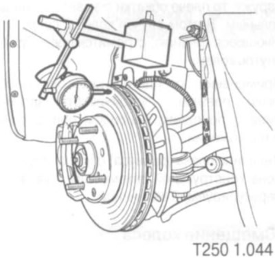
The unevenness of the disk surface is assessed by visual inspection using a pointer indicator. During operation, the presence of concentric depressions on the disk surface is allowed. The depth of such depressions should not exceed 0.40 mm.
Replacing brake pads
1. Remove the front wheel, first raising and securing the front of the vehicle using a suitable, secure support.
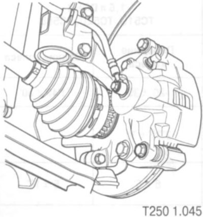
2. Using a lever (screwdriver), spread the pads. This will push the cylinder piston inward. This is necessary to prevent the pads from catching on the flange that forms on the edge of the disc as it wears out.
3. Unscrew the lower screw securing the movable caliper bracket and move the bracket upward.
4. Remove the brake pads.
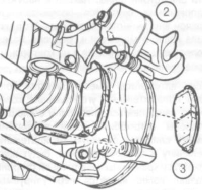
1. Screw.
2. Floating caliper bracket.
3. Brake pads.
Installation is carried out in the reverse order. Tightening torque of the floating bracket mounting screw: 27 Nm.
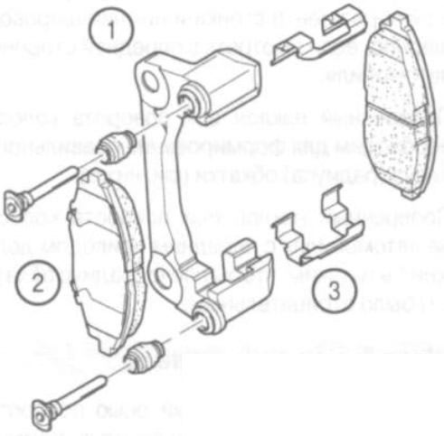
1. Fixed caliper bracket.
2. Brake pads.
3. Springs that prevent the brake pads from rattling.
Replacing rear brake pads
Replacing the rear brake pads is described in the chapter "Brakes".
Adjusting the parking brake
1. Adjust the clearance in the rear brakes by repeated (at least 10 times) on the brake pedal until the normal clearance is established.
2. Release the parking brake and make sure the drive cables move freely.
3. Move the driver's seat back to provide sufficient working space.
4. Raise and secure the vehicle so that the rear wheels can be turned.
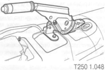
5. Remove the console trim to gain access to the lever mounting locations and the adjusting nut. To do this, remove the screw caps securing the trim to the brackets and unscrew the screws.
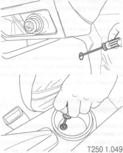
6. Adjust the tension of the parking brake cables by tightening the adjusting nut until the wheel begins to exhibit noticeable resistance to rotation.
7. Reduce the tension of the cables by unscrewing the adjusting nut until the braked wheel is completely released. This completes the adjustment.
Note: This adjustment is only for the parking brake drive. Make sure that the clearances between the shoes and the brake drums are adjusted correctly (see item 1).
The original article is on the website: CHEVYMAN.ru