


Contents: Basic information on parts… ↧ Restoring the functionality of the… ↧ Restoration of valve seats ↧ Inspection of the valve ↧ Valve grinding ↧ Lapping valves ↧
Basic information on parts restoration
For the engines described, the manufacturer provides for the restoration of the "guide bushing - valve stem" pair using valves with repair stem sizes. In this case, the worn bushing is restored by reaming to repair sizes. Work of such complexity should only be entrusted to a qualified mechanic.
Restoring the functionality of the valve guide bushing
| Size | Scan | Code applied to parts of a new engine | Code applied to engine parts during repair |
| Standard | - | - | TO |
| Repair + 0.075 | KM-253 | 1 | K1 |
| Repair + 0.150 | KM-254 | 2 | K2 |
| Repair + 0.250 | KM-255 | A |
1. Determine the actual wear in the "bushing - valve stem" pair. If the gap exceeds 0.1 mm, this friction pair needs to be replaced. This diagnostic operation should only be performed by a qualified mechanic.
2. The repair size code is applied to the valve guide bushing and the end of the valve stem. The table shows the standard and repair sizes, the designation of the reamer used by authorized service stations, and the content of the codes applied to the bushings and valves. There are two types of codes: the code applied during assembly of a new engine, and the code applied to the bushing during repair.
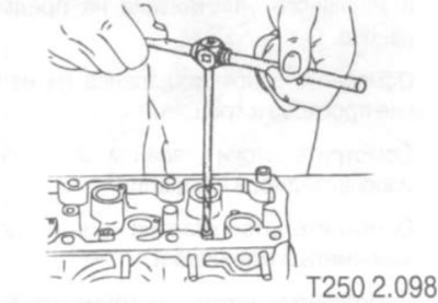
3. Ream the guide bushing hole. The reaming direction is from the top side of the cylinder head. After reaming, cross out the code on the bushing and apply a new code.
Restoration of valve seats
1. Treat the working surface of the valve seats.
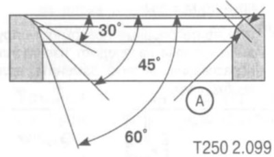
The valve seat sealing surface is restored using three conical cutters:
- milling cutter for processing the working surface of the saddle: 45°;
- milling cutter for processing the upper correction angle: 30°;
- milling cutter for processing the lower correction angle: 60°.
Width (A) of the working surface of the valve seat:
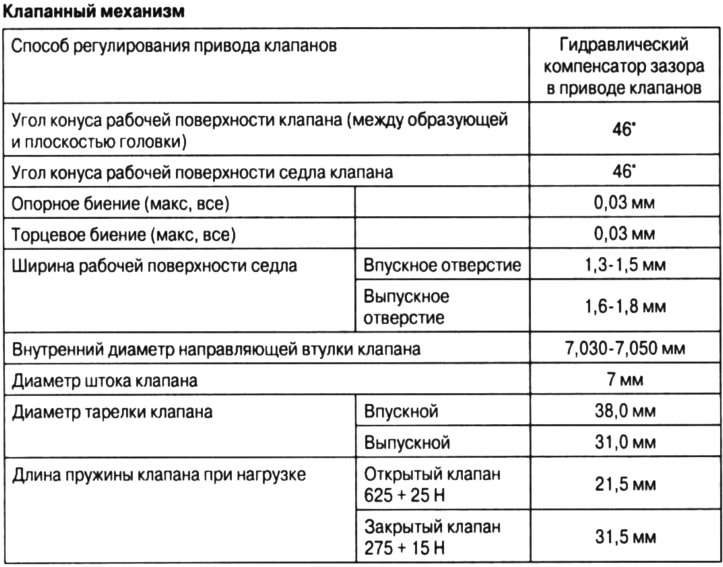
- inlet: 1.3-1.5 mm;
- outlet: 1.6-1.8 mm.
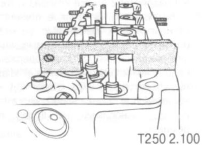
2. Check the position of the valve stem end after installing the valve (without special gauges, this work must be performed by a qualified mechanic).
3. If the end of the rod is located higher (closer to the camshaft axis), the valves should be replaced with new ones and then the position of the stem end should be checked again.
4. If the valve stem end is still higher despite replacing the valves, replace the cylinder head.
Inspection of the valve
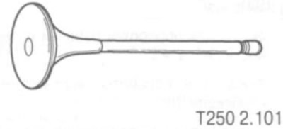
1. Inspect the valve for wear and tear, or for crushing of the upper end of the stem.
2. Inspect the valve cracker grooves and oil seal for wear.
3. Inspect the valve heads for burnouts and cracks.
4. Inspect the valve stems for wear, scoring and scratches.
5. Inspect the valve stem - it should not be bent.
6. Inspect the valve closing cone. If the wear of the contact cone is so great that resurfacing will produce a sharp edge at the junction of the conical and flat surfaces of the valve head, the valve should be replaced.
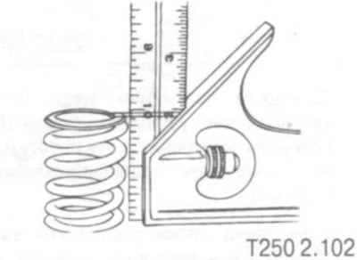
7. Inspect the valve spring. If the ends of the valve spring are not parallel, replace the valve spring.
8. Measure the valve spring height. If the valve spring height is not within specifications, replace the valve spring.
9. Inspect the valve spring seating surfaces for wear or grooving. Replace if necessary.
Valve grinding
1. Make sure there are no burnouts on the valve head cone.
2. The valve can be reground only twice. Do not ground the end of the valve stem.
3. The angle between the valve cone generatrix and the head plane is 46°.
Lapping valves
If the wear of the valve seat cone is not too great, the valve should be lapped onto a reconditioned valve seat cone (as a rule, when the valve is operating, the locking surface of the connecting rod bearings becomes wider: up to 4-5 mm). If there is no deep groove on the cone, then it is possible to grind the valve to the restored seat without grinding the cone.
The valve is ground in using special corundum-based grinding pastes.
In this case, the valve installed in the guide bushing performs reciprocating movements with simultaneous rotation to the right and left alternately. Such movements are necessary to form oblique lapping lines located crosswise. During the lapping process, the valve should be periodically rotated in the seat to ensure uniform lapping. The lapping can be considered complete when a uniform matte-gray annular contact strip equal in width to the seat lapping surface is formed on the valve locking surface.