


Note: Before removing the crankshaft, remove the flywheel (or the leading disk of the torque converter), all parts on the crankshaft nose, chain, sump, oil pump and pistons assembled with connecting rods.
1. Before dismantling the crankshaft, check the axial clearance. Install the indicator so that its leg is parallel to the crankshaft axis and touches one of its cheeks (see photo).
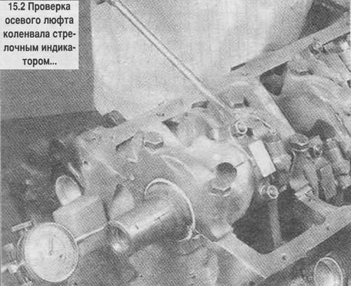
2. Move the crankshaft toward the rear of the engine, applying maximum force, and in this position set the indicator scale to zero. Then push the crankshaft toward the front of the engine and read the indicator readings. The amount of axial play is equal to the distance the shaft has moved. If the axial play exceeds the standard value, check the wear of the crankshaft thrust surfaces. If the wear is insignificant, the play should be compensated by installing new thrust half rings.
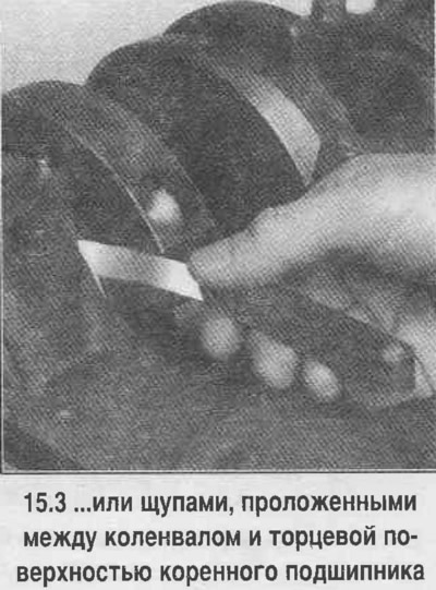
3. If you don't have an indicator head, you can measure the play using a set of feeler gauges. Move the crankshaft toward the front of the engine. Place the feeler gauge between the crankshaft cheek and the end surface of the main bearing (see photo) and measure the axial clearance, which is equal to the maximum thickness of the inserted feeler gauges.
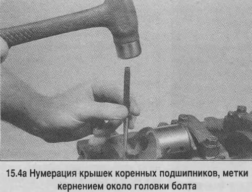
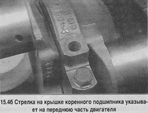
4. Check the markings on the main bearing caps, which should correspond to the cylinder number. Usually the caps are numbered starting from the front of the engine. If there is no marking, then make marks with a punch. Arrows are usually cast on the main bearing caps (see photo), which are facing the front of the engine. Loosen each of the main bearing cap bolts 1/4 turn at a time, in the reverse order shown, until the bolts can be turned by hand.
5. Using light hammer blows through a soft spacer, move the main bearing caps out of place and remove them from the engine. Do not allow the main bearing to fall out if it remains in the cap.
6. Carefully, working with an assistant, remove the crankshaft. Install the covers together with the bearings in place, tighten the bolts by hand.