


Basic braking mode
The DBC7 ABS primary braking mode used in this vehicle is a diagonally distributed system. In this system, one circuit of the master cylinder supplies pressure to the right front and left rear brakes, and the other circuit supplies pressure to the left front and right rear brakes.
All hydraulic modulator valves are in a normal, non-energized state.
Master brake cylinder. ABS braking mode - supply
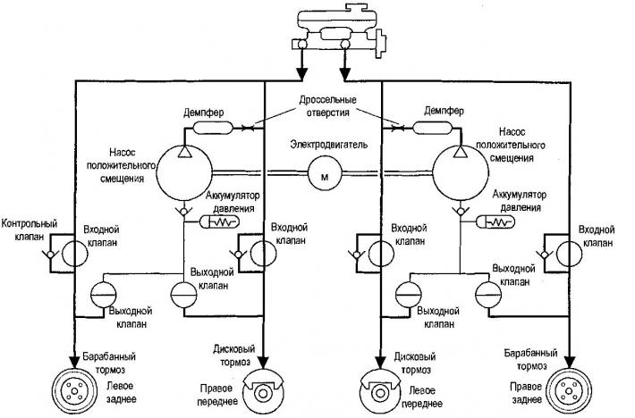
In the hold or pressure reduction mode, the ECMU detects that the wheel lock has decreased. The ECMU increases the voltage of the corresponding wheel by applying the brake master cylinder pressure. The inlet valve opens and the outlet valve closes, which allows the brake master cylinder pressure to be applied to the wheel.
Master brake cylinder. ABS braking mode - hold
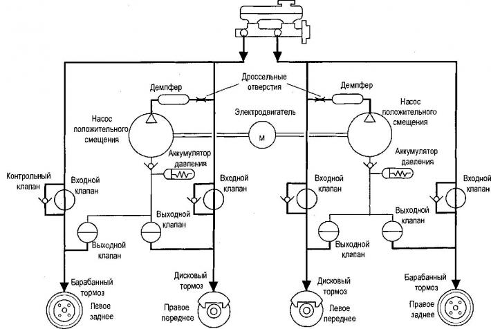
If the ECMU detects wheel lock, the ECMU closes the inlet valve and keeps the outlet valve closed in the brake pressure modulator valve to isolate the system. This keeps the brake pressure stable, so the hydraulic pressure neither increases nor decreases.
Master Cylinder ABS Braking Mode - Reset
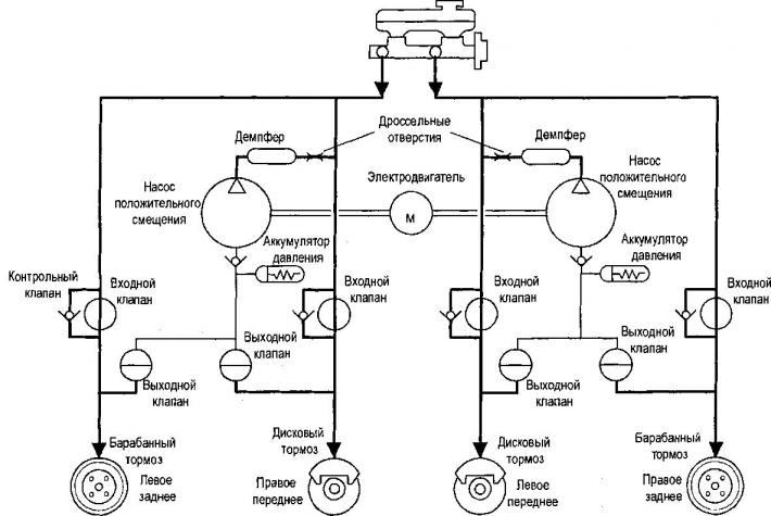
If the brake pressure modulator still detects wheel lockup during the pressure hold mode, the brake pressure modulator reduces the pressure of the corresponding wheel. The inlet valve remains closed and the outlet valve opens. Excess fluid/pressure is temporarily stored in a reservoir in the brake pressure modulator valve until the pump can return fluid to the master cylinder reservoir.
Brake Master Cylinder. DDRP
(separate dynamic metered distribution to the rear wheels)
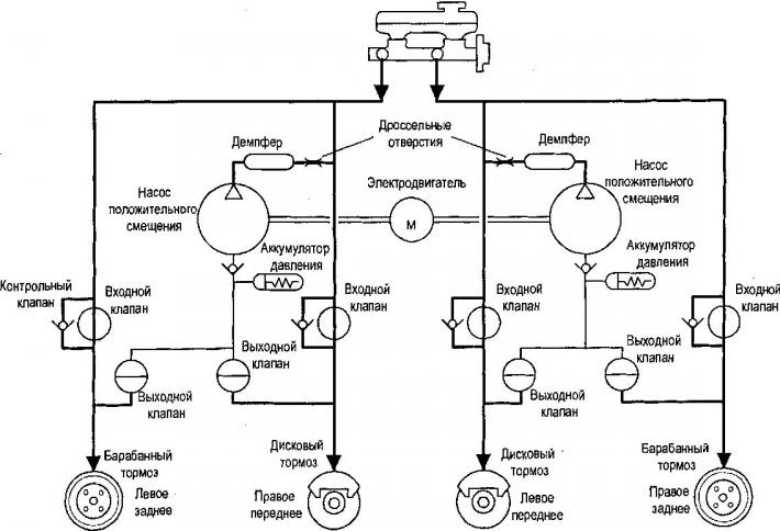
DDRP (separate dynamic metered distribution to the rear wheels) is a system for maintaining vehicle stability during braking. Under normal braking conditions, the same wheel speed must be maintained for effective and balanced braking. Under emergency braking, the vehicle requires relatively less braking force on the rear wheel because the vehicle's weight is transferred forward. DDRP maintains the required braking pressure on the rear wheel using the rear ABS inlet and outlet valves to ensure effective braking and vehicle stability. In the DDRP system, power is supplied to the rear valve from the ignition.
If the following faults occur, the red brake warning light will come on.
- Two wheel speed sensors on one axle are not working.
- Rear intake solenoid not working.
- Battery short circuit 2 (electric motor input) to ground. Battery 1 (EMC input) open or short circuit to ground.
- Open or short circuit between the electric motor and the battery.
- Open or short circuit of the ECU to the battery.
- Open or short circuit of ignition to ground.
DDRP System Malfunctions
The EMUT ensures effective braking and vehicle stability. The DDRP system supplies power to the rear valve from the ignition. The red brake warning light comes on when the following faults occur.
|
Detail |
Suspected malfunction |
DDRP |
||
|
ABS warning light |
Brake warning light |
D-DRP status |
||
|
Right Front Wheel Sensor |
Short circuit or open circuit |
On. |
- |
Partially functional |
|
Left Front Wheel Sensor |
Short circuit or open circuit |
On. |
- |
Partially functional |
|
Right rear wheel sensor |
Short circuit or open circuit |
On. |
- |
Partially functional |
|
Left rear wheel sensor |
Short circuit or open circuit |
On. |
- |
Partially functional |
|
Two sensors on one axis |
Short circuit or open circuit |
On. |
On. |
Shutdown |
|
One front and one rear sensor |
Short circuit or open circuit |
On. |
- |
Partially functional |
|
Electric motor |
Short to ground - low voltage circuit |
On. |
- |
Partially functional |
|
Short to ground - high voltage circuit |
On. |
- |
Partially functional |
|
|
Short circuit to battery - low voltage circuit |
On. |
- |
Partially functional |
|
|
Short circuit to battery - high voltage circuit |
- |
- |
No |
|
|
Electric motor circuit break |
On. |
- |
Partially functional |
|
|
Stopping the electric motor |
On. |
- |
Partially functional |
|
|
Front Wheel Clutch Solenoids |
Short circuit or open circuit |
On. |
- |
Partially functional |
|
Front Wheel Release Solenoids |
Short circuit or open circuit |
On. |
- |
Partially functional |
|
Rear Wheel Clutch Solenoids |
Short circuit or open circuit |
On. |
- |
Partially functional |
|
Rear wheel release solenoids |
Short circuit or open circuit |
On. |
On. |
Partially functional |
|
System relay |
Cliff (inability to turn on) |
On. |
- |
Partially functional |
|
Short circuit (inability to turn off) |
- |
- |
No |
|
|
Battery 2 (motor) |
Short circuit to ground |
On. |
On. |
Partially functional |
|
Breakup |
- |
- |
Low voltage |
|
|
"Mass" (Motor) |
Open or short circuit to battery |
On. |
- |
Turning on |
|
Battery 1 (ECU, solenoids) |
Open or short circuit to ground |
On. |
On. |
Shutdown |
|
"Weight" (ECU, solenoids) |
Open or short circuit to battery |
On. |
On. |
Shutdown |
|
Ignition |
Open or short circuit to ground |
On. |
On. |
Shutdown |
|
Brake switch |
Not applicable |
- |
- |
Turning on |
|
Serial communication |
Open or short circuit |
On. |
On. |
Turning on |
The original article can be found on the resource «CHEVYMAN.RU»